I think I found out the reason why Inventor Nastran is so off on the buckling load factors.
Its because the solver does not include the effects of follower force for pressure loads into the linear buckling solutions. For a loading which is not constant, but changes with the shape or orientation of the elements (structure supporting pressure loads), the displacement dependent loads (called the follower force term) needs to be computed. The follower force vector is formed for each dof in the model and appended to form the follower force matrix.
By default MSC and NX flavors of Nastran calculate this and include it with the differential stiffness, but Inventor Nastran does not.
I ran the above mentioned test problem with the MSC.Nastran with the effects of the follower force switched off for the linear buckling solution and the results match those of Inventor Nastran to less than 1% but are off from theory by the ~+30%.
So the calculation and the inclusion of the follower force matrix for loads which change with the shape and the orientation of the element in the linear buckling solution is important and the absence of this causes errors. The results from Inventor Nastran for the above mentioned test problem are an example of this.
Another example which can be illustrated (which has been discussed at length on this forum) is this:
Link
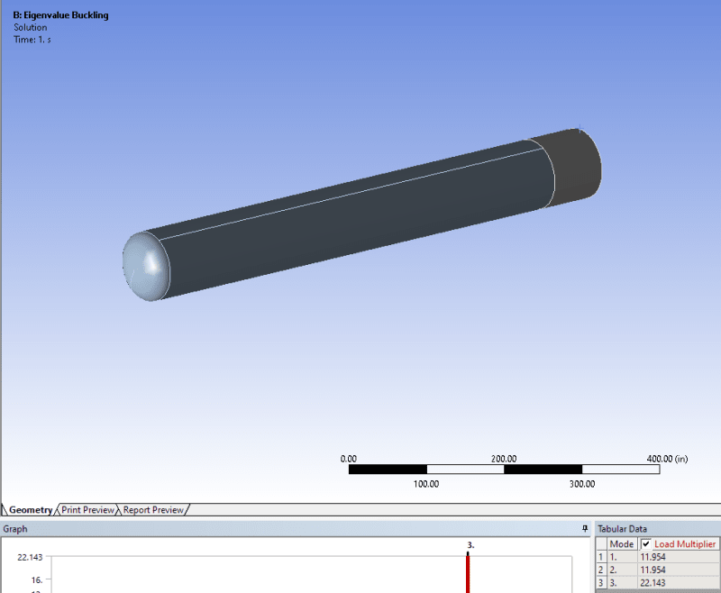
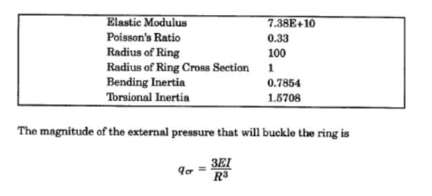
Let us take a test case as shown below:
(Note: All values given above are in SI)
Per Roarks the buckling pressure is given as:
qcr = 3*E*I/R^3 = 1.74E+05 N/m
Doing a linear buckling analysis in MSC.Nastran:
qcr = 1.71E+05 N/m
So the results match theory to ~2%
Doing a linear buckling analysis in Inventor Nastran:
qcr = 2.09E+05 N/m
The results are off theory by ~20%
It looks like Inventor Nastran would require the user to do a full fledged geometric non-linear analysis to compute the buckling load. This would include the follower force effects. But doing this for a linear problem just because the linear buckling solution fails to include the follower force terms sounds to me like a huge over-kill!!