Eng-Tips is the largest engineering community on the Internet

Intelligent Work Forums for Engineering Professionals

  • Congratulations waross on being selected by the Tek-Tips community for having the most helpful posts in the forums last week. Way to Go!

Differential Gearbox complicated to Calculate speed shaft 1

Status
Not open for further replies.

sidpred

Mechanical
Feb 7, 2005
4
0
0
AR
Hi Guys, Hopefully you can help me find answers to my questions

I am looking for how to calculate the speeds of each of the output shafts.
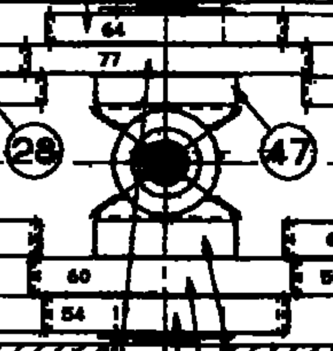
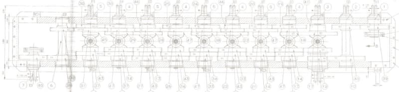
This reducer has two drive shafts and eleven output shafts on the opposite side. Each of the shafts has two planet gears.
What is the relationship between the input side and output side planetariums? Would it be one? In other words, does the shaft rotate at the same speed on each side?


reductor_diferencial_psm7j7.jpg
 
Replies continue below

Recommended for you

Your scan is unusable and I'm not going to put any effort into making it legible. As a practical note I'd expect all the speeds to be the same because they haven't changed the physical size of each diff unit, if the torque was multiplying (say) then they would have to get progressively bigger.

Cheers

Greg Locock


New here? Try reading these, they might help FAQ731-376
 
If this is a roll form line then either they all turn the same speed or there is a uniform progression (like 3% per stand)
If you know the gear ratios then you can figure it out.

= = = = = = = = = = = = = = = = = = = =
P.E. Metallurgy, consulting work welcomed
 
I've cleaned a bit - see this file:
It escapes me where the differential is. It looks like one motor directly drives a continuous chain of gears on the input side and the other drives the outputs directly on the output side and there might be bevel gears that link them, but there's no carrier to float the difference in speeds. I should be able to lock any shaft, turn one shaft, and have the remaining shaft turn, but I don't see how this drive does it based on the picture.

I'm guessing that [3] and [13] are inputs? That would make [3]-[13] as outputs and because they used the same &^#&@^&$ numbers for both sides ... that's terrible drafting practice.
 
It just looks like 2 90 degree changes in the turning axis - an idler rather than a differential. Lock the gear at the top and it will lock the bevel gear which will lock the gear at the bottom - unless there is some other part that's not well described by this drawing.
 
The two triangle shaped gears resemble the spider gears of a differential. The drawings exclude any details of a carrier. Sometimes it's fun to do a puzzle.
 
Status
Not open for further replies.
Back
Top