Eng-Tips is the largest engineering community on the Internet

Intelligent Work Forums for Engineering Professionals

  • Congratulations waross on being selected by the Tek-Tips community for having the most helpful posts in the forums last week. Way to Go!

Dimension is incorrect?

Status
Not open for further replies.

Barnon

Mechanical
Jul 23, 2016
97
0
0
US
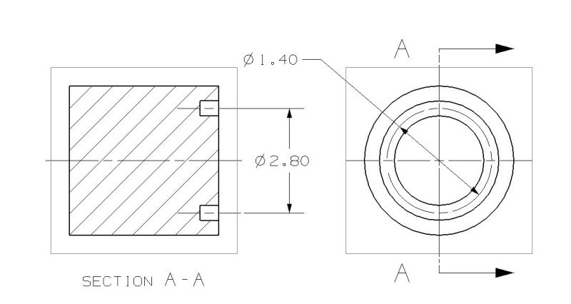
The pic below shows the center-line of a groove on the right and the correct dimension of 1.40 dia. The section view on the left shows 2 2D centerlines with a cylindrical dimension that shows 2X the correct value. What's up with that? Happens with NX9.0 and NC11.0.
dimension_qyuqxh.jpg
 
Replies continue below

Recommended for you

can you upload the part? I can't replicate in my example.

Anthony Galante
Senior Support Engineer


NX3 to NX11 with almost every MR (24versions)
 
This is a good old option for those who create large revolved models, that large and complex that it is suitable to only show half of the section. (- jet engines etc.)
Then IF you select the centerline ( ONLY centerlines will do this) as the FIRST selection AND ONLY for cylindrical dimensions, NX will double the value.
Then you toggle OFF that extension line and the Arrow , you have a dimension which is OK by the standards.
If you select the arc center instead of the centerline object , it will not happen.

That setting has been there as long as i can remember.

2017-06-05_15-29-52_wgokyt.png


Regards,
Tomas
 
What @Toost says is a very common situation where I would want a smart dimension to behave exactly that way. Most other CAD packages require overriding the dimension, breaking the relation, or at least used to.
 
Ok thanks guys. I can't seem to edit that option. The only way I can find it is to search in customer defaults and the when I select it I get the error below.
error_oqt62i.jpg
 
Hi,

IF you have the rights to change the drafting standard you can do following.
[ul]
[li]Switch Default level to Site[/li]
[li]Unlock the setting (small lock on the right of the line)[/li]
[li]Select the "Customize Standard" Button[/li]
[li]Now you should be able to find it under Radial if I'm correct[/li]
[li]Ok on both menu's and it should be saved[/li]
[li]Restart NX for the changes to take effect[/li]
[/ul]

Keep in mind that if the site settings are locked you need to ask you administrator to make the change for you.


Ronald van den Broek
Senior Application Engineer
Winterthur Gas & Diesel Ltd
NX9 / TC10.1.2

Building new PLM environment from Scratch using NX11 / TC11
 
Thx Ron
It's all greyed out. I've got the administrator looking into it. It's odd though, here at work we are on 11.0 but at home I have 9.0 and I can change that setting but even after changing it and restarting NX it still doubles the value when dimensioning to centerlines. Guess I just need to stop doing that.
 
Barnon said:
It's all greyed out

This means you don't have write access to the DPV file.

Ronald van den Broek
Senior Application Engineer
Winterthur Gas & Diesel Ltd
NX9 / TC10.1.2

Building new PLM environment from Scratch using NX11 / TC11
 
It's as Ronald says, The "Site" or the "group" level has locked the customer defaults on your work. (You do not have access to the file in windows.)
which you have at home, but i guess that you are trying this on existing partfiles , which i guess that the setting doesn't affect unless you also toggle :
NX11 :
Customer defaults - Drafting - General/ Setup - Workflow -Drawing -Settings origination = Drawing standard.
( = "use the customer defaults" instead of "saved settings in the partfile":)

NX9:
Customer defaults - Drafting - Drawing - General -Drawing Settings - Use settings from standard.


Regards,
Tomas
 
I am running NX9 and the setting that controls doubling the dimension values to Symmetrical Centerlines is under Drafting -> Annotation -> Radial tab (not in the Drafting Standard) and happens to be unlocked at the User level.

NX9 DoubleSymmCenterline.png

Barnon said:
Guess I just need to stop doing that.

No, possibly just put the radial/diametric dimension in the top view, add a note that it's to the groove center and move on or try a vertical or perpendicular dimension and prefix it with a diameter symbol if it MUST be shown in the section. Unless you are ALWAYS detailing small parts with no tiny intricacies that need detail views, I would recommend NOT changing the setting - as soon as you do, you'll need the other one for a detail view where you cannot show the full diameter of the area you're trying to dimension.

Tim Flater
NX Designer
NX 9.0.2.5 Win7 Enterprise x64 SP1
Intel Core i7 2.5GHz 16GB RAM
4GB NVIDIA Quadro K3100M
 
Status
Not open for further replies.
Back
Top