Eng-Tips is the largest engineering community on the Internet

Intelligent Work Forums for Engineering Professionals

Dimensions in Sketches 9

Status
Not open for further replies.

randy64

Aerospace
Jul 31, 2003
170
0
0
US
Hello. Just wanting to get some opinions on something I've run across recently.

When updating dimensions in a sketch, I change the dimension. I do this because I like a "clean" sketch. For example, if the dimension is .50 and I'm making it .25 longer, I change the dim to .75.

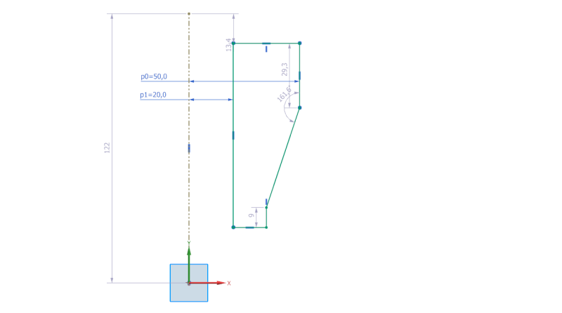
I recently was working on a sketch created by a coworker. In his sketch the dimension was .50+.25. When I asked him about this, he said that that was his way of keeping track of the changes he was making. At first, this went against my instinct of having an uncluttered, clean sketch, but the more I've thought about it, it might make sense to do it that way.

Am I letting my OCD get in the way of a good technique, or is it best to leave a clean sketch as my legacy to others?

Your thoughts please.
 
Replies continue below

Recommended for you

@loki3000
When I first started with NX, I was trying to dimension the centerline of a revolve feature for diameter, like in SolidWorks. Then I found out that you can't actual do that in NX, which baffled me because it is such a convenient feature. But I adapted by simply dividing the diameter value by 2. Still would prefer being able to dimension the centerline and hope it would be implemented in the future.
 
Hi Loki3000,

It's not easy like SolidWorks but I often use make symetric then cylindrical dimension to do the job

make_symetric_mhdtnx.jpg


Regards
Didier Psaltopoulos
 
I do like Didier but I select the
entire profile and then convert
the mirrored profile to reference.
that way I see the feature shape.
 
I must be totally missing something. You can dimension any line pretty much any way you want in NX...
I revolve sketches about their reference axis all the time and it is a breeze. Maybe we are not on the same page.
sketch_ii9qwx.png


Felix K. Holloway - Designer - NX 9 & 11 Native
 
Right, I don't see why you cannot dimension to the centerline instead above. screw shaft would be 1.25 and top corner of head would be 3.5. I'm confused why people think it's not possible or easy to do this.

Felix K. Holloway - Designer - NX 9 & 11 Native
 
Felix,

Because we're all different and will never agree that everything should be done one way every single time - that's why. Some people just prefer to see the entire profile in their sketch and work with the diametric values to avoid any possible confusion or mistakes that might happen during calculating the radial values. Others, like yourself, can function just fine by working with the radial profile only.

Pretty much the same non-issue that it has been since Sketcher was introduced.

Tim Flater
NX Designer
NX 9.0.2.5 Win7 Enterprise x64 SP1
Intel Core i7 2.5GHz 16GB RAM
4GB NVIDIA Quadro K3100M
 
As we always used to say, "With UG (NX), the GOOD news is that there are always 10 ways to do something. The BAD news is that nine of them are perfectly valid."

John R. Baker, P.E. (ret)
EX-Product 'Evangelist'
Irvine, CA
Siemens PLM:
UG/NX Museum:

The secret of life is not finding someone to live with
It's finding someone you can't live without
 
Yes, repeating the same thing over and over and over - some do it one way, others do it another.

Tim Flater
NX Designer
NX 9.0.2.5 Win7 Enterprise x64 SP1
Intel Core i7 2.5GHz 16GB RAM
4GB NVIDIA Quadro K3100M
 
Thanks for the replies all! Your totally right about individual preferences, just how it goes even under the same company roof.

Understanding that, what my confusion was alluding to was loki3000's statement that it cannot be done. When in reality it can, although the function is not the same in the comparison software (SW).

Great quote John, I will remember that one when I am tutoring the next employee we get on NX.

Felix K. Holloway - Designer - NX 9 & 11 Native
 
Felix,

I could be wrong, but I believe what other users are saying CANNOT be done in NX Sketcher is two fold:

1.) Dassault CATIA v5 & Solidworks Sketchers allow line(s) to be labelled specifically as an Axis, meaning that line is recognized as something more than a line in a sketch, which NX does NOT do - we only refer to that sort of line as an axis - it doesn't change any sketch behavior at all.

2.) NX Sketcher recognizing a true Axis and then allowing for diametral dimensioning without additional geometry. Using NX, we "work around" this "limitation" by mirroring the Sketch geometry and making it reference or using a point on the opposite side and THEN dimension between the curves - Dassault apparently doesn't require that from my understanding.

In all, whatever Dassault is doing in its sketchers, it is removing some steps from the process that NX users have to go through to achieve basically the same end result when diametral values are desired. I believe that is what users are saying cannot be done in that specific manner.

Hope that makes sense.

Tim Flater
NX Designer
NX 9.0.2.5 Win7 Enterprise x64 SP1
Intel Core i7 2.5GHz 16GB RAM
4GB NVIDIA Quadro K3100M
 
Hi Tim, that is exactly the answer I was looking for, felt like I was grasping at thin air there for a bit. Thanks a lot for posting that! Great to know. I've never thought it as a hindrance and my mind just works the way NX does now so very interesting to hear comparisons from the other systems.

Felix K. Holloway - Designer - NX 9 & 11 Native
 
Also keep in mind what Didier points out in that dimensions inherited on drawings may need to have the diameters shown, which can be inherited from the NX Sketch. Another reason why some "can't" use radial sketch dimensioning.

Tim Flater
NX Designer
NX 9.0.2.5 Win7 Enterprise x64 SP1
Intel Core i7 2.5GHz 16GB RAM
4GB NVIDIA Quadro K3100M
 
Status
Not open for further replies.
Back
Top