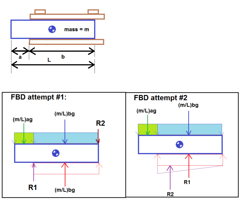
I'm analyzing a pallet holder where the load (mass = m, length = L, assumed to be a rigid body) rests between the top and bottom plates (it's just slotted in there, the top plate isn't weighting the load down in any way). The load is also secured laterally with a slight slip allowed but just looking at the vertical load case at the moment. See diagram below. The load is able to overhang forward of the edge of the plates (overhanging length = a, supported length = b = L-a). To start with, I'm assuming the load has uniform mass distribution (it actually is non-uniform and I know the CG location, however I'm already having trouble with a uniform distribution so I'd like to start there).
Can someone help me with the FBD for the load? It seems like a simple problem however I'm having trouble convincing myself of the correct approach.
(Distributed loads shown as thin lines with the sum shown as a thicker line. For ease of visualization, the weight of the load is color coded with unsupported and supported lengths in green and blue respectively.)

Attempt #1:
[ul]
[li]My first thought was that the weight of the supported length is directly reacted by a normal force (i.e. (m/L)*b*g in both directions). [/li]
[li]The weight of the unsupported length is then reacted by a point load at the corner where it overhangs (R1).[/li]
[li]But then there's an unbalanced moment. I've decided that this would be reacted by a point load coming from the upper plate onto the aft end of the load (R2).[/li]
[li]The other option for reacting the unbalanced moment could come from the lateral restraint, however because the slip in the lateral restraint is larger than the clearance between the load and the top plate, I'm assuming this isn't the case.[/li]
[/ul]
Attempt #2:
[ul]
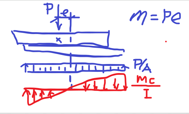
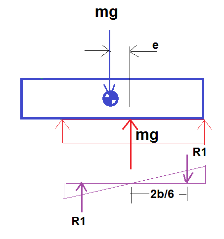
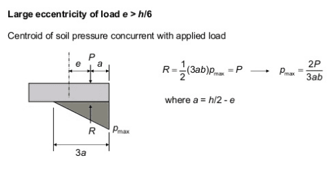
[li]The normal force is 'skewed' towards the overhanging side of the load supported length is still primarily reacted with a normal force, but now it's no longer equal to the supported length's weight.[/li]
[li]R2 located at 2/3*b from the right hand side. R1 located at 1/2*b [/li]
[/ul]
Do either of these seem reasonable? Or is there something else to consider?
Then, my real load has a non-uniform mass distribution with the CG still between the plates but further towards the forward (LHS in the diagram) side. I could adapt either attempt #1 or #2 by idealizing the weight as a point load at the CG to calculate the reactions, however adapting attempt #1 would involve having to assume/calculate the supported mass & CG vs unsupported mass & CG.
Can someone help me with the FBD for the load? It seems like a simple problem however I'm having trouble convincing myself of the correct approach.
(Distributed loads shown as thin lines with the sum shown as a thicker line. For ease of visualization, the weight of the load is color coded with unsupported and supported lengths in green and blue respectively.)

Attempt #1:
[ul]
[li]My first thought was that the weight of the supported length is directly reacted by a normal force (i.e. (m/L)*b*g in both directions). [/li]
[li]The weight of the unsupported length is then reacted by a point load at the corner where it overhangs (R1).[/li]
[li]But then there's an unbalanced moment. I've decided that this would be reacted by a point load coming from the upper plate onto the aft end of the load (R2).[/li]
[li]The other option for reacting the unbalanced moment could come from the lateral restraint, however because the slip in the lateral restraint is larger than the clearance between the load and the top plate, I'm assuming this isn't the case.[/li]
[/ul]
Attempt #2:
[ul]
[li]The normal force is 'skewed' towards the overhanging side of the load supported length is still primarily reacted with a normal force, but now it's no longer equal to the supported length's weight.[/li]
[li]R2 located at 2/3*b from the right hand side. R1 located at 1/2*b [/li]
[/ul]
Do either of these seem reasonable? Or is there something else to consider?
Then, my real load has a non-uniform mass distribution with the CG still between the plates but further towards the forward (LHS in the diagram) side. I could adapt either attempt #1 or #2 by idealizing the weight as a point load at the CG to calculate the reactions, however adapting attempt #1 would involve having to assume/calculate the supported mass & CG vs unsupported mass & CG.


