Eng-Tips is the largest engineering community on the Internet

Intelligent Work Forums for Engineering Professionals

Does a profile control the overall length of a surface

Status
Not open for further replies.

Blue33

Mechanical
Oct 22, 2018
6
0
0
US
I have a feeling this is a basic question, but I have always wondered it. A profile tolerance zone boundary looks exactly like the surface, just offset by the value, but what happens at the extents of the boundary? does the boundary stretch and contract to match the actual part? if a part is too long and goes beyond the extents of the nominal boundary, is in or out of tolerance?

My work computer is not letting me upload an image here. So picture this...you have a simple cube with three of the faces as datums A,B,C. one of the faces that is perpendicular to A is controlled by a profile to ABC. The face that is opposite Datum A is controlled with a parallelism to A (not sure this matters but I thought I'd mention it). Is the location of the face parallel to A controlled? or do I need a size dimension on the overall width of my block?

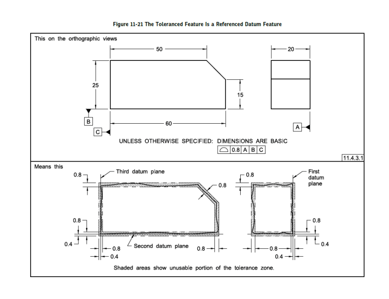
Any reference to where in the standard this concept is outlined would be helpful.

thanks
 
Replies continue below

Recommended for you

Assuming ASME and profile of a surface are being used, profile can control the location of the surface, but it doesn't need to. If the distance between A and the parallel surface is located with a +/- tolerance, the +/- tolerance should locate the surface and profile becomes a refinement of orientation and form. If the dimension is a basic dimension, profile controls the location of the surface as well as the orientation and form. This is described at least generally in Section 8.2 of ASME Y14.5 2009.
 
I just ran across some articles online that confirm what I thought I heard on this forum recently, that you can only locate features of size with a +/- tolerance. I'm not sure where this example falls. The two opposed surfaces are a feature of size, but the individual surface that you would be locating is not a feature of size. If we take the route that it is not a feature of size, it sounds like you must use profile of a surface to locate the surface parallel to A.

Bottom line: I would recommend locating that surface using profile instead of +/- tolereances.
 
Those seem to be two questions:

1) There is the assumption that the profile tolerance zone can be extrapolated from the nominal border limits but I don't recall much discussion in the ASME Y14.5 standard about that.

2) Parallelism does not control location.

I presume you are trying to say that the boundary of the surface controlled by the profile tolerance would control the opposite face? No, it does not. The surface affected by profile is considered stopped where there is a sudden change in curvature.
 
A picture sure would help (try it from home rather than work?) but the reason I mentioned the two different standards is because you asked "what happens at the extents of the boundary". I was thinking of Fig. 11-5 in ASME, where the intersection point of two adjacent surfaces creates a tolerance zone that extends outward from there -- see the attached graphic (this shows a unilateral tolerance, but the idea about that sharp corner is clear).
ISO would see that corner's tolerance differently, where imaginary spheres with a diameter matching the tolerance value are used to construct the zone at the intersection of the two surfaces. The result is that it doesn't extend out as far on the corner.

Maybe that doesn't apply here, since you went on to ask about parallelism and location, etc. But in reading your first couple of sentences in the original question, my thoughts went to this idea of extrapolating profile at a corner.
 
 https://files.engineering.com/getfile.aspx?folder=f3879b23-7953-4f27-894f-950a949682b7&file=SharpCorner.png
In ASME Y14.5, see "Fundamental Rules" (4.1 in the 2018 version):

"(o) UOS, all tolerances and datum features apply for full depth, length, and width of the feature."

That means that tolerance zones must be extended enough to cover the entire considered surface as produced.
 
That's not the meaning of that statement in the standard and you are reading it backwards somehow.

The OP is asking if the size of one feature is a limitation on the location of another. Your argument above is that it isn't.

Now you change your position and say that this is not the case? Or you don't understand the original question?
 
Thanks for all the replies...the other post was really helpful as well. I feel like I have an answer so I'll sum up my thoughts to all the posts.

Garland23...sorry should have mentioned...this ASME Y14.5

donatim24...In my real world situation I have a BASIC dimension that is giving the location of this surface. If what you say and the profile on the surface that is perpendicular to it does control it's location, I would assume it only controls the location in one direction, the positive material direction, since that would be beyond the extent on the profile boundary. But if the surface went in the negative material direction, it would still fall within the profile boundary. I definitely agree that a +/- dimension on this location or profile of surface is ideal, just trying to understand what it means if it is left off of a drawing.

In the other post it is talking about the surface that actually has the profile on it, and whether it is acceptable if it is within the "extended boundary". I can see where that is more a product of undefined geometry and what it can allow. Hence the reason to have fully defined geometry. In my cube example, the parallelism would keep the block from turning into a wedge, but does it keep it from getting X inches wider or X inches shorter?

If I assume the boundary extends infinitely, then my block can get as wide as it wants. Almost like an implied MIN. No good! I'll put some control on it.
If I assume the boundary does not extend at all, then it could get shorter because it will stay within the boundary. Almost like an implied MAX. No good! I'll put some control on it.

When I wrote my original post I was only thinking about the getting wider part, but now I see the getting narrower part. So to me regardless of what the standard defines or how we interpret it, both interpretations allow a situation I don't like, because ultimately the part is undefined.

I appreciate everyone's comments!!
 
Blue33,

I would add the following information. In ASME Y14.5 2018 the profile tolerance explainations are better and there are new ways to control the location. The way profile controls the location vary depending on your datum selection and if you use all around or all over. It made me better understant some principles.

Here is a picture similar to your case. As yu can see, the face opposed to datum A is located. the face can not go behond the plane 20.4mm opposite to datum A. I hope it's clearer.

profile_tolererance_xndmzb.png

Gee
 
Blue33,

Profile tolerances control whatever faces you applied the profile to. If you apply profiles to the front and rear surfaces, your length is one of the things you have controlled.

--
JHG
 
Status
Not open for further replies.
Back
Top