Eng-Tips is the largest engineering community on the Internet

Intelligent Work Forums for Engineering Professionals

  • Congratulations waross on being selected by the Tek-Tips community for having the most helpful posts in the forums last week. Way to Go!

Does D/B > 6 for static and D/B <6 for dynamic balance always work, as suggest per API 610?

Status
Not open for further replies.

Mech5656

Mechanical
Aug 2, 2014
126
0
0
US
Hell Dear Engineers,

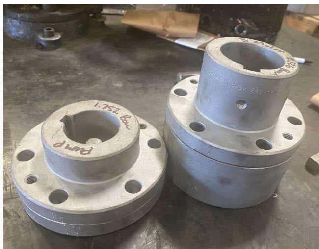
We have a vertical inline pump here that failed probably because of rotor unbalance.

Based on impeller sizes (Impeller OD:13.75” and width 0.5”), D/ B=27.5 since it is greater than 6, it should be static balance (which we did during previous repair about a year ago).

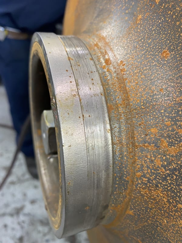
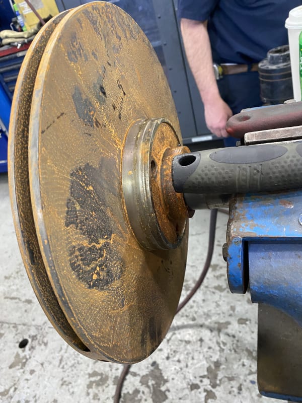
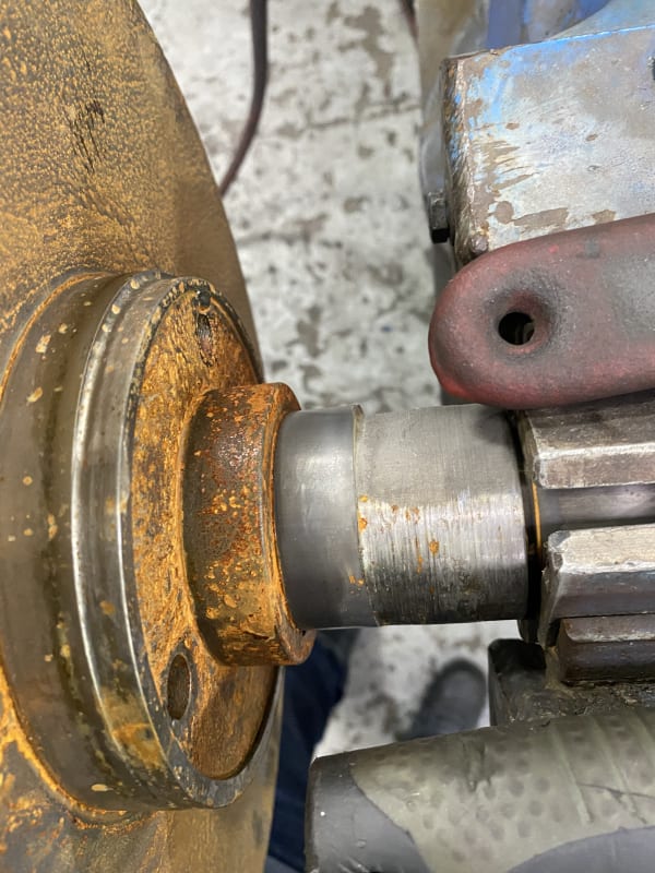
The pump rotor lost its center position during operation and rubbed to throat bushing and wear rings (please see attached pictures). Would you suggest dynamic balance even if D/B is greater than 6?

EDIT:
I wanted to add some more details to this post. Per API 610, impeller can be static balanced if D/B is greater than 6 and it can be dynamic balanced if D/B is less than 6. Where D is impeller diameter and B is shroud width of impeller at impeller OD.

Have you experienced a case where an impeller (for vertical inline pump) was static balanced but it was supposed to be dynamic balanced? What kind of damage was found on impeller? Thanks for reading.


IMG_6565_le94km.jpg


IMG_6567_rrhltz.jpg


IMG_6568_r1iggr.jpg


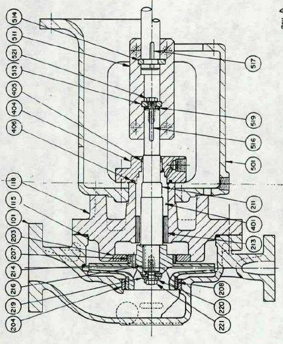
Pump assembly drawing.

Capture_nibmwt.jpg
 
Replies continue below

Recommended for you

Dear Engineers,

Do you have any suggestions on the root cause of this issue?
Here is what I think about it. Looking at pump assembly drawing, the heavy rub on throat bushing (item 213) (smallest clearance area) and eventually the rub on wear rings can be caused by one of the following.


-There was hydraulic imbalance meaning that the pump was ran too off from BEP, where hydraulic forces on impeller were not balanced and made the rotor move, hitting the throat bushing.
-Impeller was not balanced and was jumping around hitting the throat bushing ID.
-Any thing else?

 
That style of coupling is prone to causing poor shaft run-out. I have seen these assembled with one of the keys turned the wrong way, causing very high shaft run-out. On some of these, there is not enough room above the mechanical seal to take a good shaft run-out measurement with everything assembled. For that case, I would assemble the shaft, coupling and impeller, hanging vertically in the shop. I would verify that the run-out on the lower impeller wear ring was acceptable before putting the assembly into the pump case.

These pumps are often single volute designs. As you said, running this pump at very low flow or very high flow could side load the impeller and result in hard rubs.

I would still perform a two plane balance on that impeller even if API says it is not necessary.

Johnny Pellin
 
I'm not a pump guy. I would trust whatever Johnny said.

fwiw, it seems like a low L/D to me so I doubt static balancing caused the problem.

The rust I guess accumulated after it was removed from service.

I'm assuming piece 213 is the throat bushing.

That means there are no bearings on the pump side of that coupling. I'm not familiar with that kind of construction. It looks like a long distance to the closest bearing (the closest bearing isn't even shown on the drawing). I'd think that would make the impeller very susceptible to side movement due to that flexibility of that long unsupported shaft. The coupling might perhaps contribute to that shaft flexibility even though its' supposed to be rigid. At least that's what comes to my mind being a non-pump guy. I'm a little curious if this is a common construction or if the wear rings are supposed to "act like" bearings (I know I've heard they do in multistage pumps).

The rub on the shaft at location of piece 213 throat bushing looks like it's only one one arc of the shaft. Maybe that suggests something like a transient.

=====================================
(2B)+(2B)' ?
 
You are correct, Pete. This is a rigidly coupled vertical in-line pump. The pump has no true bearing. The nearest bearing is the lower bearing in the motor. Deep wear on one side of a shaft suggests a bent shaft. Improper assembly of that rigid coupling causes the shaft to be kicked off to one side, creating the same effect as a bent shaft. This does not look like a failure caused by imbalance. The coupling is the most likely source of the problem.

Johnny Pellin
 
JJPellin,

Thanks for replying to this post. I apologize because the assembly drawing shown is old and the pump does not have rigid coupling anymore (it was upgraded).

Here is the type of coupling the pump has (showing pump coupling hub and motor coupling hub separately). I still stand with my original comment that the root cause is probably imbalance because the impeller was 1-plane balanced (per API 610) not dynamic balanced.

Capture123_krjuxe.jpg
 
No. It does not have a clam shell coupling. But, the coupling in the picture is still a rigid coupling, just a different type. I do not believe that a pure couple unbalance resulting from a single plane balance would cause the damage you have shown. I still think it is a shaft run-out problem and probably resulting from problems with the rigid coupling.

In some ways, the coupling in the picture is worse than the one in the drawing. At least the clam shell coupling can be tightened to an interference fit on both shafts. The coupling in the picture requires a slip fit on the motor shaft in order to be able to assembly the hub over the split ring.

Johnny Pellin
 
Your theory about hydraulic imbalance does not work either. If the shaft was pushed off to one side because of running too far from BEP in single volute pump, the damage to the bushing would be on one side, but the shaft would be grooved all the way around. Deep damage on one side of the shaft and all the way around the bushing is a classic indication of shaft run-out (bent shaft).

Johnny Pellin
 
I have never seen that style of coupling used in a vertical in-line pump. That coupling is common in big vertical turbine pumps where the shaft is under considerable tension. I don't believe that coupling is a good choice or appropriate for a vertical in-line pump. It does not provide enough radial stiffness since both hubs are a loose fit on their shafts. If the pump were to experience up-thrust from high suction pressure or from running beyond end of curve, that coupling would let the shaft buckle off to the side, resulting in the sort of damage you show.

Johnny Pellin
 
Hello JJPellin:

Firstly, thank you for taking interest in this issue and providing your suggestions.

Just so I understand correctly, the coupling shown above is flexible coupling not rigid coupling because it does not have shims (spring type allowing it to be flexible) in between the motor and pump hubs correct?

The shaft run-outs were measured (on V-blocks) during previous repair about a year ago and they were within 0.001" (as API 610 suggests).

This coupling shown has 0.001"-0.002" interference fit against motor shaft (will be heated up to install) and has 0.001"-0.002" clearance (loose fit) against pump shaft.

I missed to mention the case on this pump has two opposite cut waters (volute lips). Doesnt that make the flow more balanced during operation? I will re-check if the damage on shaft is all around or just one area.

Here are the corrections made this time for assembly of pump:
[ul]
[li]Dynamically balance impeller instead of 1-plane balance.[/li]
[li]Carefully check shaft runouts before assembly and make sure they are within 0.001"[/li]
[li]Make sure coupling interference fit against motor shaft and clearance against pump shaft is within 0.001"[/li]
[li]Runouts of rotor will be checked and alignment will be checked during assembly.[/li]
[/ul]

Thanks for the reply again.

 
Unless I am missing something, that is a rigid coupling, not flexible. It does not have any disk packs, rubber elements, diaphragms or other flexible components. If the motor hub is an interference fit, that is better than a loose fit. Normally, those are a slip fit. I am not sure how you remove that hub. I guess you heat it up, slip it on too far, install the split ring in the groove in the motor shaft and then pull the hub down over the split ring before it cools. In order to remove it, you have to drive it up, press it up or heat it quickly so you can slide it up to get the split ring back out. Strange.

You are correct that a double volute pump will be less prone to side load the impeller if run away from BEP.

The pictures above clearly show that the damage is much deeper on one side of the shaft and one side of the impeller wear rings.

Good luck. After the pump runs, please come back and let us know if the changes you made solved the problem.

Johnny Pellin
 
Hello JJPellin,

Thank you again for replying. During pump assembly, I noticed another issue and (since I had posted about this pump) I want to share it to see if you have any feedback or experienced this in the past.

During repair, the coupling assembly (rigid type with multiple pieces) was welded on both pump and motor bores and machined for clearance and interference fit mentioned above. The mating faces of all coupling items were also skim cut within 0.001 TIR.

Now, during assembly, when the coupling is assembled, we are getting runouts of 0.005" on bottom impeller ring (see above assembly drawing) when indicator is placed on case cover (also called head).

Even though the faces were with 0.001 to bore, when they are assembled and bolted, they force the shafts go away from being straight. See below. Currently we are checking runouts on those faces, marking high spots with sharpie and removing them by stone faces. Any recommendation on alternative type of coupling to use here based on your experience in past?


P3020852_gkdqyl.jpg
 
Coupling Corporation of America makes an adjustable rigid coupling. You adjust a ring of setscrews to dial in very close to zero runout. We have a dozen or so in service.

Johnny Pellin
 
Status
Not open for further replies.
Back
Top