Eng-Tips is the largest engineering community on the Internet

Intelligent Work Forums for Engineering Professionals

Does this use of multiple datum features make sense? 9

Status
Not open for further replies.
Replies continue below

Recommended for you

When the programmer tries to implement this it gives him an error message.

Error-CMM._w5kxzw.jpg
 
I would have to disagree with @greenimi. Datums A and B do not share a common axis. To use that type of call, they would have to share a common axis to constrain the required 3 degrees of freedom together being a primary datum.

PC-DMIS_Capture_x5kafg.png
 
From the theory point of view, as long the two axes are basic apart I would argue it is a valid callout.
If some specific software is giving you errors that means its programming engineers did not align it with th he applicable standard's theory.
If those two axes are coaxial means they are zero basic apart (zero not shown). But, again, could be any number/value apart not neccessary zero
 
Chris said:
To use that type of call, they would have to share a common axis to constrain the required 3 degrees of freedom together being a primary datum.

I would also disagree with Chris that a common axis is needed.
You can use a common plane for this type of callouts A-B and those planes can be basic dimension from each other.
 
Since the features that are being evaluated are cylinders, this does not work. If B was a plan on the end of the tube, then yes it would work since A and B would contact the mating surfaces simultaneously, but this is not the case with this design. As far as the measuring software goes, PC-DMIS GD&T evaluations are developed using the math definitions set forth by ASME Y14.5.
 
The situation we are talking about is called "Multiple Datum Features" (2009) or "Common Datum Features" (2018).

In both standards datum produced from MDF / CDF can be:
[ul]
[li]Single Datum Plane[/li]
[li]Single axis of Two Coaxial Features.[/li]
[li]Pattern of features of Size at MMB[/li]
[li]Pattern of features of Size at RMB[/li]
[/ul]

So, no, two planes basic distance apart will not cut it. Same with two axis distance / angle apart.


"For every expert there is an equal and opposite expert"
Arthur C. Clarke Profiles of the future

 
Hi All,

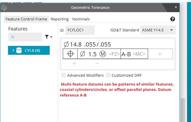
I would say that the A-B reference is okay in terms of compliance to the ASME Y14.5 standard. The combination of A and B creates a valid multiple datum feature (now called a "common datum feature" in ASME Y14.5-2018). It looks like the issue is that the CMM software does not support that particular combination.

There are other things on the drawing that I would have issues with:

1. It's hard to tell whether the end of the part is at PT A or not, because the extension lines for the dimension look identical to the object lines for the part geometry.

2. The profile tolerances on the two ends of the part don't control the location of the end surfaces (because they each reference only the local axis). So these tolerances end up only controlling the orientation and form of the end surfaces, and thus could have been Perpendicularity tolerances instead. If the intent was to control the relative locations of the end surfaces, then the profile tolerances should have referenced A-B instead.

3. The profile tolerance between PT A and PT D is not compliant with Y14.5. Profile is not to be used in conjunction with a directly toleranced diameter dimension, and the annotation BOUNDARY is not used with profile tolerances either. Y14.5 defines a type of position tolerance with the BOUNDARY annotation, so the tolerance should have been position instead of profile. It looks like the intent was to control the outer surface of the part with a single boundary, between PT A and PT D (including the bends). Unfortunately Y14.5 doesn't address this situation yet - the boundary position tool is only defined for regular features of size (cylinders and parallel-plane widths).

4. The position tolerances on cylinders A and B each reference the toleranced feature at MMC and reference the datum feature A-B at RMB. Since the datum feature includes the toleranced feature, I would say that the toleranced feature should be referenced RFS. I've always thought that this type of partly self-referencing callout is conceptually dubious in the first place (even though Y14.5 illustrates it), and mixing the modifiers makes it even more so.

5. The A|B|C datum feature reference in the profile FCF is overconstrained. Cylinder A constrains 4 degrees of freedom, and cylinder B would constrain the other two rotation around axis A and translation along axis A). So there are no DOF's left for feature C to constrain. If the intent is to have feature C constrain axial translation, then the reference needs to be A|C|B.

6. I would say that it doesn't make sense to tolerance A and B together to A-B (so that neither one takes precedence over the other) and then reference them A|B in the profile FCF (so that A takes precedence over B). Whatever the constraint situation that A and B experience in the assembly is, it should be used consistently.

It's interesting how the tolerancing techniques defined in ASME Y14.5 are confounded by a pipe with two bends in it.


Evan Janeshewski

Axymetrix Quality Engineering Inc.
 
In this drawing, A does control 4 degrees of freedom, 2 rotation (rotation around X and rotation around Y) and 2 translation (X and Y origin). B only can control one degree of rotation (rotation around Z), C controls the only degree of freedom left which is a translation (Z origin).

-.-. .... .-. .. ... -- -.-. -.-. ..- .-.. .-.. --- ..- --. ....
 
CH,

Fig 11-18 /2018 might not support your points above

If the left planar surface is A and the right one is B.
Left surface A is defined with profile to A-B
Right surface is definex with profile to A-B.

Do you think my case is the same or different (from the mathematical defonition) with the current figure 11-18 shown in 2018 standard?

If different, why (reasons) my case would not be valid, acceptable to the y14.5 (2009, 2018) rules?
 
greenimi,

How exactly are you going to check features A and B against A-B and how it will be different from what is already shown on 11-18?

Now if we look at OP case, how datum / feature / simulator for A-B will look like? It isn't the common axis of A and B, isn't it?

"For every expert there is an equal and opposite expert"
Arthur C. Clarke Profiles of the future

 
Hi, CheckerHater:

I have to agree with Greenimi. There is nothing on the OP's print that requires checking features A and B against A-B.

A-B works fine as long as relationship between features A and B are fully (BASICly) defined. They don't have to be coaxial or common axis.

Best regards,

Alex

 
A small part of this problem is the standard, particularly lacking an exact example dealing with this situation. A large part is not having a reliable understanding of the useful limitations and just tossing constraints at the problem and hoping someone else can figure it out.

The typical approach is to reduce the problem to a simplification involving axes which discard the bulk of the information available. However the root problem is managing the entire surface boundary, an area that falls under the mis-named "profile" tolerance. It should be "surface deviation tolerance," but the name is less important than the use.

There is an idealized surface boundary / profile within which the entire surface needs to fit and some local boundaries that set the appropriate cross-section (another failure in Y14.5 is that Y14.5 doesn't control geometric characteristics like area or rate of change of geometric characteristic from one section to another.)

In this, there's no need to identify any overall datum reference frame for the pipe. The profile tolerances can share a simultaneous condition with a null set for the datum feature reference set with separate requirements for the local boundaries. Simply find if the part fits entirely within that overall constraint without sequential application of constraints. As the saying goes "If it fits, it ships."

Users do like to overconstrain the solution by adding DRFs so that they can more easily program CMMs to validate it, resulting in accepting a smaller set of usable parts than would otherwise be accepted, aka tossing usable parts into the garbage.
 
John-FR,

Constraining tubes is a pain in the ass.

Your datum features[ ]A and[ ]B over constrain your part. They might work if your part is flexible. How would you build the fixture?

If this were my part, I would keep your outside diameter datum feature[ ]A. I would use the end as datum feature[ ]B. I would use the first bent side as datum feature[ ]C (a clocking feature), and I would apply a positional tolerance to the opposite diameter, and a profile to the opposite end.

--
JHG
 
Status
Not open for further replies.
Back
Top