Continue to Site

Eng-Tips is the largest engineering community on the Internet

Intelligent Work Forums for Engineering Professionals

  • Congratulations GregLocock on being selected by the Eng-Tips community for having the most helpful posts in the forums last week. Way to Go!

Doing some calculations on Oceangate Titan sub 3

Status
Not open for further replies.

jpitz31

Mechanical
Jul 9, 2023
13
Hello Everyone, I am trying to do some calculations on components on the Oceangate Titan sub.
I am a software engineer with a Composites Manufacturing background.

I am trying to calculate the amount of PSI that was on the bonding flange on the Titan sub. I have used the formula 2π(35 + 30)(35 - 30 + ) r1 = 35, r2 = 30 3 = height. r1 = 35 inches, r2 = 30 inches height is 3 inches to calculate the bonding surface area.

I am using 5800 PSI for the pressure.

Sorry I am working in PSI and inches instead of SI units.

In order to calculate the psi on the surface area of the joint bond, I need to calculate the pressure on the hemispheric ends.

I am using Hemisphere Calculator on Calculator soup. I am not sure of which surface area to use.

I understand that I have to multiply the Hemisphere surface area by the depth.

Then Once I know the PSI I can divide this by the surface area of the bonding joint.

Go easy guys and gals I am not a mechanical Engineer.

Any help with the proper formulas needed would be great. Not sure if I am correct with what I have so far.

Thanks

Joe


Replies continue below

Recommended for you

The force on the joint, caused by pressure, is the same regardless whether the head is flat or domed.
 
jpitz31 said:
Not sure if I am correct with what I have so far.

You're not.

Regards,

Mike


The problem with sloppy work is that the supply FAR EXCEEDS the demand
 
Since I want to calculate the joint bonding area, should use the surface area of just the end cap or the entire length of the pressure vessel?

Thanks

Joe
 
I'd calculate the "joint bonding area" as the actual area of the joint, whatever its configuration


The problem with sloppy work is that the supply FAR EXCEEDS the demand
 
Not intending to be rude, but it sounds as though you are unclear on the calculation you are trying to perform. Users of this site who you are asking questions of are likely less clear than you are.

Suggest you carefully review and state your assumptions, make sketches if needed and present unambiguous questions. More likely to get somewhere that way :)

The problem with sloppy work is that the supply FAR EXCEEDS the demand
 
The pressure would be the area of the end (as a circle)in (in^2) x pressure in psi. This is the longitudinal compressive force the cylinder. The stress would be the force divided by the x-sectional area of the cylinder. I don't know how the stress varies across the wall thickness. The projected longitudinal projection in (in^2) x pressure in psi divided by 2 (since there are two walls) will give you the radial compression in the cylinder. For thin cylinders this is closely approximated as a linear compression stress. For thicker walls the stress varies from a maximum at the interior fibre of the cylinder and reduces as you go to the exterior fibre.

-----*****-----
So strange to see the singularity approaching while the entire planet is rapidly turning into a hellscape. -John Coates

-Dik
 
I agree with dik and will elaborate as follows

The longitudinal compressive force is the external pressure times the projectred area of the hemispherical head (the projected area lies in the vertical plane). 5800 psig sounds about right for the depth as P( in psi) = density of water (62.4 lb/cu ft) x depth (ft) divided by 144. Since the stress in the longitudinal direction is equal to the force divided by the area in the longitudinal direction then:

Stress = F/A = P (Pi) D2/4 divided by (Pi) D t = PD/4t

The circumferential hoop stress is due to the pressure acting on the longitudinal projected area of the vessel. The horizontal projected area of the vessel varies along its length so therefore does the compressive hoop stress. If the diameter was constant the hoop force would be:

Force = PDL where L is length of vessel

Pressure = F/A = PDL/2Lt = PD/2t Where t is wall thickness of vessel So this will be the maximum stress at the widest section of the vessel.

These above stresses are true for a thin wall cylinder

However with a thick wall cylinder there is also a radial componnent to stress on the vessel acting normal to the surface, based on a limiting D/t ratio. The method of calculation are found in the literature.

For the pressure on the flange connection of the head then take the pressure on the projected area of the diamter of the vessel plus flange diameter extension and find the projected area so force on area is

Force = P x A = 5800 x (Pi) D2/4 Where D is combined diameter of flange plus vessel in inches and A is the combinde area

Pressure on flange = P/Aflg = P (Pi) Do2-Di2 divided by 4 Where Do is outside diameter of connection flange and Di is the inside diameter of connection flange.
 
Thanks everyone for the great posts, @Snickster you mention "The method of calculation are found in the literature."
Can I assume that this literature is the Engineering Handbook?

Thanks again

Joe
 
Could someone work these formulas for me so I can verify my answers.

I would like to calculate the pressure of the entire end cap
I would then like to calculate the pressure on just the flange bond.

I am using the following data:

Pressure 5800 psi
Length = 3 inches (end cap bond length that overlaps the carbon fiber tube
thickness of carbon fiber tube = 5 inches
Outer diameter of carbon fiber tube = 70 inches
Inner diameter of the carbon fiber tube 60 inches
The extension of the flange diameter, guessing about .100 inch for bonding thickness.

Thanks in advance

Joe


I doubt you'll be able to come up with a meaningful number.
Where you have a change in geometry (cylinder to hemisphere), you develop bending stresses and shear stresses at the junction.
For homogenous thin material, these forces/moments can be calculated- see Formulas for Stress and Strain or Timoshenko's Theory of Plates and Shells.
For a "thick" shell, those methods will not be accurate. For composite materials with differing properties in different directions, those methods will not be accurate.
Where there are differences in material (carbon fiber to titanium), thickness, varying material properties in different directions (in the carbon fiber), thermal stresses through the material, differential thermal expansion due to differing materials, etc., you wind up with a rather involved problem. You can neglect various aspects and come up "a number" but whether that relates to the actual design is questionable.
 
Yes can be found in engineering Mechanics of Mateials textbooks - also do search for Thick Wall Cylindrical Pressure Vessels on web. Calcs get a little complex.
 
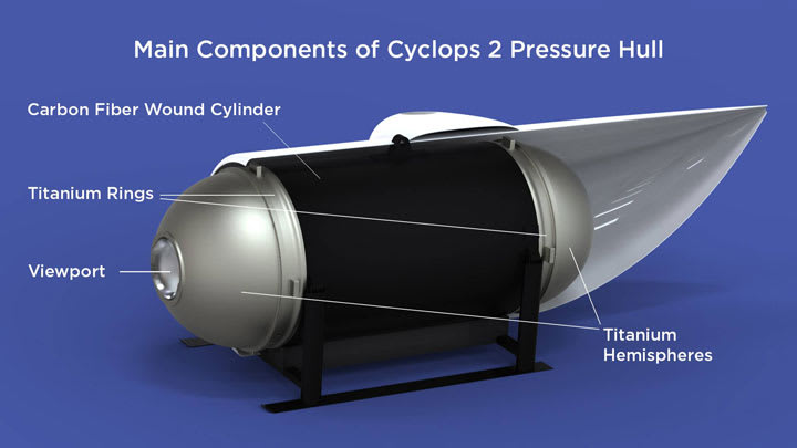
You would need to show me a diagram of the components you are referring to for me to calculate. It is easy to caluculate the pressure and resulting forces bsed on simple static analyis, but as JStephen indicates calculating the actual stresses developed in the members may be more complex than just a straight hoop stress or longitudinal stress calculation given the unconventional shape and materials involved.
 
Regardless of what you calculate for stresses, you also need to keep in mind that buckling of cylinders is purely a function of the Young's Modulus, the length, the cross-sectional area, and the moment of inertia.
 
Don't think the OP has the technical knowledge to appreciate the depth of the subject referred to by both JSteven and TGS4.

No offense to the OP intended.

The problem with sloppy work is that the supply FAR EXCEEDS the demand
 
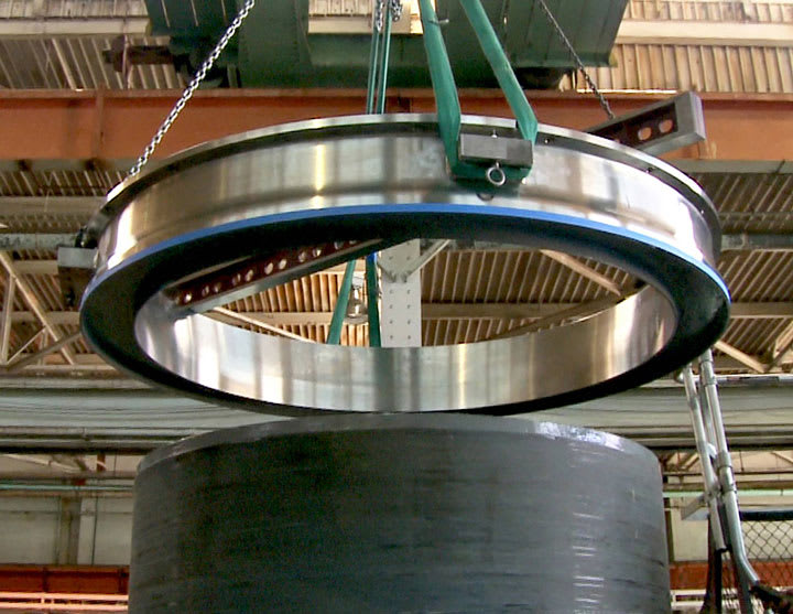
@Snickster, let me know if this ok, I am trying to get my head around some of the basic formulas. If it too involved I more than likely will not be able to reproduce it at this basic level of my understanding.

Thanks


cutaway_nismzn.jpg
web-flange_hdpw7s.jpg
 
@ jpitz31
Do you have a solid background in pressure vessel design, manufacturing and inspection?
You are very confused.

Regards
 
No I do not have a solid background in pressure vessel design, manufacturing and inspection. I am a software engineer with a background in composites manufacturing. But I am try to learn some basic engineering formulas.

Joe
 
Status
Not open for further replies.

Part and Inventory Search

Sponsor