Eng-Tips is the largest engineering community on the Internet

Intelligent Work Forums for Engineering Professionals

  • Congratulations waross on being selected by the Eng-Tips community for having the most helpful posts in the forums last week. Way to Go!

Doing some calculations on Oceangate Titan sub 3

Status
Not open for further replies.

jpitz31

Mechanical
Jul 9, 2023
13
US
Hello Everyone, I am trying to do some calculations on components on the Oceangate Titan sub.
I am a software engineer with a Composites Manufacturing background.

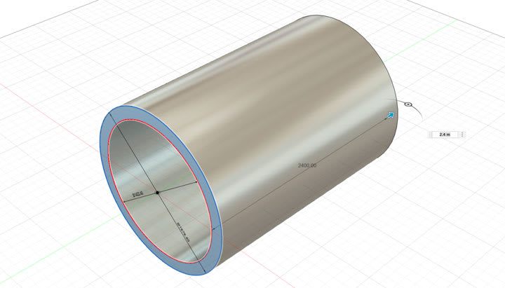
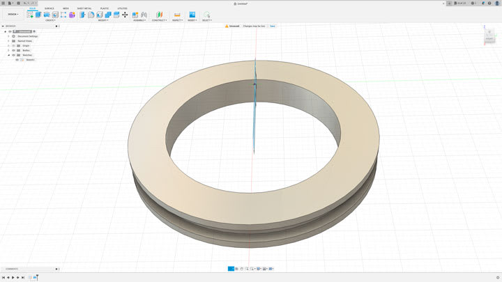
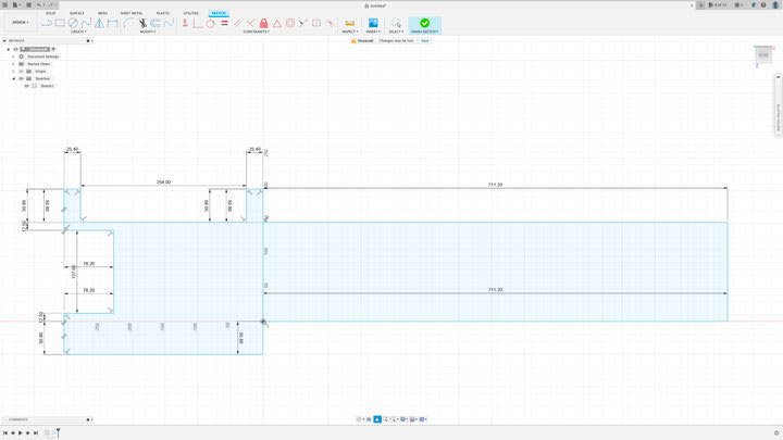
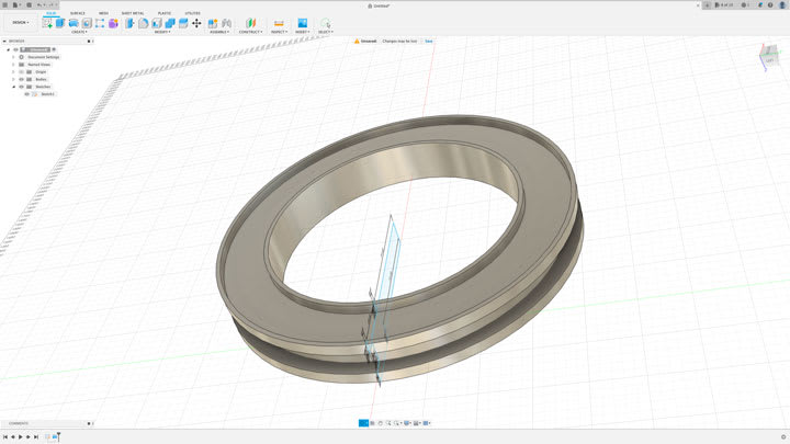
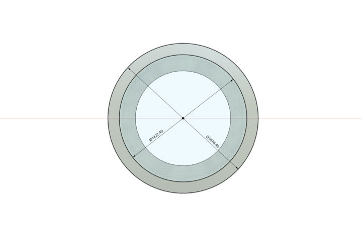
I am trying to calculate the amount of PSI that was on the bonding flange on the Titan sub. I have used the formula 2π(35 + 30)(35 - 30 + ) r1 = 35, r2 = 30 3 = height. r1 = 35 inches, r2 = 30 inches height is 3 inches to calculate the bonding surface area.

I am using 5800 PSI for the pressure.

Sorry I am working in PSI and inches instead of SI units.

In order to calculate the psi on the surface area of the joint bond, I need to calculate the pressure on the hemispheric ends.

I am using Hemisphere Calculator on Calculator soup. I am not sure of which surface area to use.

I understand that I have to multiply the Hemisphere surface area by the depth.

Then Once I know the PSI I can divide this by the surface area of the bonding joint.

Go easy guys and gals I am not a mechanical Engineer.

Any help with the proper formulas needed would be great. Not sure if I am correct with what I have so far.

Thanks

Joe


Replies continue below

Recommended for you


@r6155 Pretty interesting, you do not even know me and you are trying to label me. I work with composites, and the general public have a lot of misconceptions on what composites can do and what they cannot do. I am trying to educate the general population away from misconceptions
and what better way then to use a current event that generates a lot of interest. We all know that Oceangate did not follow standard methodology or safety protocols. This is not my fault nor I did cause the accident.

By educating people I can try to remove any negative connotations concerning the engineering and manufacturing of the composites industry.

The only reason this is a tragedy is because you have an engineer who's ego is way too big and he has fooled himself, for whatever reason, to not believe his engineering training.

So keep your opinions to yourself, as I really do not care what your opinion is. If this was not such a beneficial group , I would tell you what you can do to yourself.


It's a learning experience... I was curious to see where this would go.

-----*****-----
So strange to see the singularity approaching while the entire planet is rapidly turning into a hellscape. -John Coates

-Dik
 
You should get a copy of Timoshenko's Theory of Plates and Shells and study it.

But even that won't get you far enough - you really need to read (a lot) of studies done on damage and failure mechanisms of submerged fiber composite shells.
 
jpitz31,c I'd say you need to start with something much more basic, like engineering statics material. Available all over the net.

The problem with sloppy work is that the supply FAR EXCEEDS the demand
 
I am not sure if I understand the photo. So each titanium end head connects to a titanium transistion ring that then connect to the composite vessle. So at the connection point of the head to the ring is a 3" wide flange and at the connection to the composite side a 5" wide flange? And if so what are the OD and ID of the flanges? Can you provide a dimensional sketch?
 
Here are the drawings, The flange dimensions are a total guess, The carbon cylinder is taken from wikipedia.

Thanks

Joe
Flange5_jpzbs2.jpg
Flange3_zkk3tg.jpg
flange1_rndzjh.jpg
Flange2_z7bxe2.jpg
Flange4_l6uy7d.jpg
 
I still can't make out the dimensions of the flange as they are too small to be visible and the end cap is not even shown, or at least I can't tell as nothing is labeled. Anyway it is very simple to calculate the compressive force and pressure acting on any section of the vessel.

For the longitudinal sress in the wall, cut a vertical slice at the point desired. Multiply the hydrostatic pressure of 5800 psi times the total crosssectional area of the slice even the area not filled with any material (this is called the projected area). Then divide by the actual net material area of the slice.

For instance for a cut through the carbon fiber vessel the pressure in the fiber wall (which is actuall the compressive stress) =

Total Force divided by Net Material Area of crossection

Total Force = P x total area of slice = 5800 (Pi/4) (70)[sup]2[/sup] = 22,321,015.8 pounds

Divided by the net material area of the slice =

Pressure/Compressive Stress in Carbon Fiber wall = F/A = (22,321,015.8) divided by (Pi/4) (70[sup]2[/sup] - 60[sup]2[/sup]) = 17,170 psi compressive stress in carbon fiber wall.
 
Note that if the bearing suface of the titanium flange on the carbon fiber wall is not the full thickness of the carbon fiber wall then the local stress at the contact point will be a little higher based on the actual bearing surface area of the flange on the carbon fiber vessel wall. However in short distance the higher local bearing surface stress should spread out to equal the stress calculated above on the crossection material of the carbon fiber wall. A finite element analysis can be used to determine how the higher bearing pressure spreads out/flows. An approximation would be that the actual maximum pressure stress at the juction of the flange to the carbon fiber would be the total force calculated above divided by the contact area of the titanium flange to the carbon fiber wall. The local bearing stress spreads out pretty quickly to the entire carbon wall section due to the transfer of bearing stress to the adjacent material by shear.
 
Also remeber that there are circumferential stresses and radial stresses present. In the carbon fiber vessel the circumferential stress is the total force divided by the net material area in the horizontal plane =

Pressure x total horizontal projected area of slice divided by the net material area, in this case the slice will be cut down the horizontal centerline of the vessel

Total Force on Project Area = P x D x L Where D is outside diameter and L is length of carbon fiber vessel

= 5800(70)(2400/25.4) = 38,362,205 pounds

Circumferential Pressure/Stress in wall = F/A where A = 2tL where t is wall thickness of carbon fiber

= 38,362,205 divided by 2(5)(2400/25.4) = 40,600 psi

Also there is a radial stress due the vessel being a thick wall rather than thin wall vessel, therefore there is three dimension normal stress components in the wall of the carbon fiber (and possible some shear?). However I am not sure if the radial would be same as calculated as those equations found for thick wall metal pressure vessels because of the different material properties of the carbon composite. I am not an expert in detailed 3 dimensional stress analysis.
 
Status
Not open for further replies.

Part and Inventory Search

Sponsor

Back
Top