Continue to Site

Eng-Tips is the largest engineering community on the Internet

Intelligent Work Forums for Engineering Professionals

  • Congratulations KootK on being selected by the Eng-Tips community for having the most helpful posts in the forums last week. Way to Go!

Door Frame Canopy Supported by thin Z-Girts 1

Status
Not open for further replies.

onlym112

Structural
Sep 9, 2019
45
Hi everyone,

I have a small canopy frame made with L102x102x6.4 and bent plates above a door frame. The canopy needs to be connected to the Z-girt that has thin 3mm walls. As a connection EIT, I do not feel comfortable connecting a canopy that is to carry snow load to a flimsy Z-girt that is supported by sag rods along its length. I brought this concern to the EOR and asked him to provide me with a detail of how this is going to work and he simply replied to me by telling me to bolt or weld to the girt. I understand he is the one who designed the girts and the canopy but this doesn't sit well with me. Am I missing something here? Below are some pictures to show you my situation.
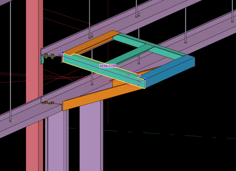
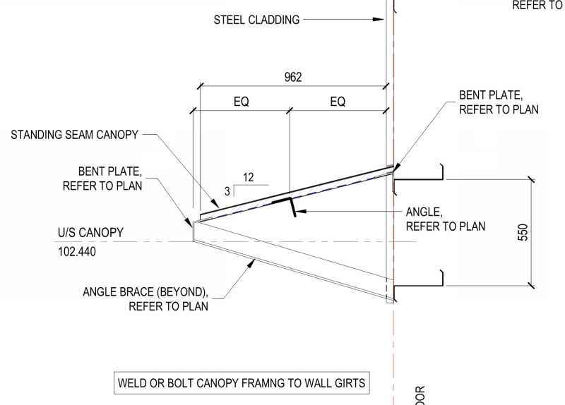
CVS_Canopy_tqh0bo.png


CVS_Canopy_Detail_gi8rdv.png
 
Replies continue below

Recommended for you

Who is stamping the connection calcs?

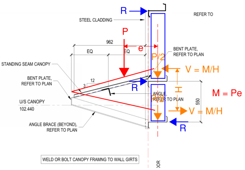
I think the main issue is loading the girts eccentric to their shear center without any provision to handle the torsion or local flange bending. It might work better to add vertical members between the struts, then attaching the canopy to the vertical members. That way the vertical load will go through the girt weak-axis shear center and the eccentricity will be resolved through a couple acting at the girt strong-axis shear center.
 
Here is my previous comment in sketch form. The blue rectangles are the added vertical members. R is the horizontal reaction of the vertical members acting on the girts. Technically the vertical loads would be less than P/2 for this setup, but you could conservatively ignore the contribution of the third girt at the top.

Screenshot_2023-12-11_185532_durqhc.png
 
I agree with Bones, but IMHO, the EOR should be giving you the vertical members.
 
My supervisor will be the one stamping all of my connection designs. I am in agreement with XR250 that I shouldn't be the one inserting those vertical members. I do not know how this girt is behaving, the loads it is experiencing, its stiffness, its capacity and other things that the EOR considered when designing these girts. I believe he should be directing me more clearly as to what to do instead of just telling me to weld or bolt onto the girt which I don't really have much room to do that either and I am not comfortable doing that. Too many unknowns and doesn't seem right.
 
You are right to be concerned. A zee member in a wall of a PEMB is normally a wind girt, not meant to support gravity loads.

I would either add vertical members each side of the door which extend down to the foundation wall, or add two horizontal members which span column to column. And I mean hot rolled members, not zee girts.

DaveAtkins
 
If you aren’t comfortable with providing connections as directed by the EOR, it would not be unreasonable to suggest a different configuration. Just say you can make connections work if it’s configured like this, is this acceptable to the EOR, and if so please provide vertical member size.

Hopefully your supervisor is available to weigh in on this as well.
 
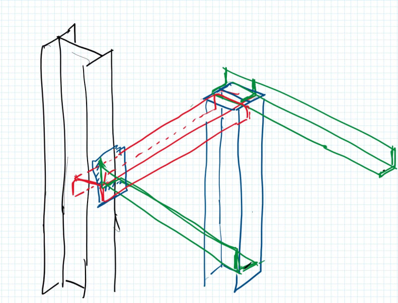
Could you enhance the door frame and connect it laterally to the portal-column
and attached the cantilever arms to it as shown below ?

236_i56hdc.jpg
 
DaveAtkins said:
A zee member in a wall of a PEMB is normally a wind girt, not meant to support gravity loads.

I would either add vertical members each side of the door which extend down to the foundation wall, or add two horizontal members which span column to column. And I mean hot rolled members, not zee girts.

I agree this would be a preferred load path, but in this case the global load path is being set by the EOR and the OP has little control over it. Presumably the EOR would have checked the girts for weak axis gravity loading.
 
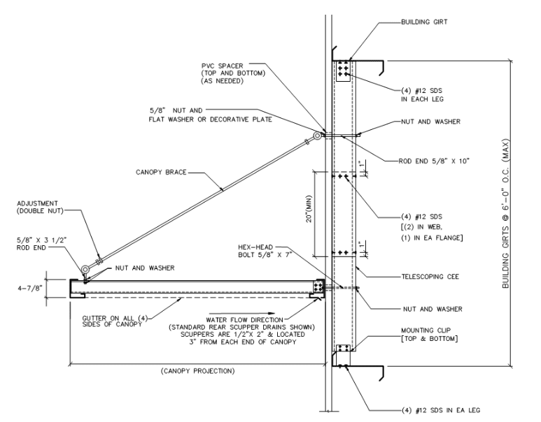
These type of canopies are added to PEMB type buildings all the time without requiring any complex analysis. Lots of companies sell canopies like this "off the shelf" that are just installed anywhere on a PEMB building. Presumably, the off the shelf canopies are aluminum and very light. May not apply to your project if it gets heavy.

PEMB_Canopy_bx300h.png


What makes it possible is that the steel wall panel carries the vertical load to the foundation. I don't have experience with how they work in high snow areas but they hold up to wind no problem.
 
Exactly why the EOR should have been providing the vertical member.
 
SandwichEngine, that’s interesting that these pre-engineered canopy guys rely on the wall panel axial strength. Their installation sheet shows all the canopy rafters located within the width of the door opening. So the girt would still need to act as a header to carry that entire canopy load out to the wall panel “jambs”. Can’t see that working for any significant snow load.
 
Thank you everyone for your input and advice. I will go back to the EOR..
 
Status
Not open for further replies.

Part and Inventory Search

Sponsor