JustASoftwareGuy
Electrical
Hey everyone - I'm new here. I'm in the process of building a model railroad layout, and am starting to get to the wiring/electronics phase, and need a little guidance. Years ago, I was an electrical engineering student, but it seems I forgot everything I learned back then! (maybe that's why I switched to computer science after two years?)
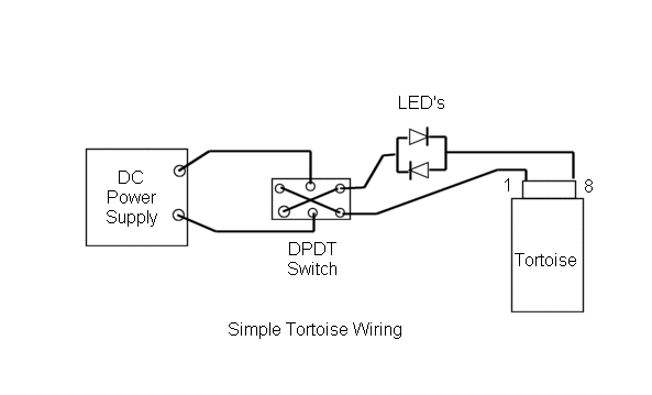
This is probably an extremely simple question - but here goes anyway. I am trying to wire up a motor, with a DPDT switch, and 2 LEDs. I'm using bipolar LEDs, so the idea is that when one is red, the other green, and when the switch is thrown, the colors reverse, etc etc. I am going off the schematic below, and in general, it works. I'm using a 12v power supply. The issue I'm having, is when the LEDs are in the circuit, they seem to be drawing around 4 volts of power from the motor. Without the LEDs, I measure 12v at the poles of the motor, but only 8v with the LEDs. I would like to give the motor a bit more juice than 8 volts, as it's a bit too slow.
So, my question is... is there any way I can get more voltage to the motor, while keeping the 12v power supply? I'm willing to sacrifice brightness of the LEDs if need be. Is the alternative to just get a 16v power supply?

(before I posted this, I re-read the instructions of the motor, and it actually says that each LED added in series, will reduce the voltage to the motor by 2 volts. It also says you may want to increase the power supply to compensate. So, there's my answer I guess, but I'm posting this anyway in case anyone here has any other clever ideas)
Thanks!
W
This is probably an extremely simple question - but here goes anyway. I am trying to wire up a motor, with a DPDT switch, and 2 LEDs. I'm using bipolar LEDs, so the idea is that when one is red, the other green, and when the switch is thrown, the colors reverse, etc etc. I am going off the schematic below, and in general, it works. I'm using a 12v power supply. The issue I'm having, is when the LEDs are in the circuit, they seem to be drawing around 4 volts of power from the motor. Without the LEDs, I measure 12v at the poles of the motor, but only 8v with the LEDs. I would like to give the motor a bit more juice than 8 volts, as it's a bit too slow.
So, my question is... is there any way I can get more voltage to the motor, while keeping the 12v power supply? I'm willing to sacrifice brightness of the LEDs if need be. Is the alternative to just get a 16v power supply?

(before I posted this, I re-read the instructions of the motor, and it actually says that each LED added in series, will reduce the voltage to the motor by 2 volts. It also says you may want to increase the power supply to compensate. So, there's my answer I guess, but I'm posting this anyway in case anyone here has any other clever ideas)
Thanks!
W
