Eng-Tips is the largest engineering community on the Internet

Intelligent Work Forums for Engineering Professionals

  • Congratulations waross on being selected by the Tek-Tips community for having the most helpful posts in the forums last week. Way to Go!

Drawing error ? 1

Status
Not open for further replies.

Rwelch9

Mechanical
Apr 22, 2020
116
0
0
GB
Hi guys,

IMG_20200605_223348_trfix9.jpg

Please see attached drawing from our customer.

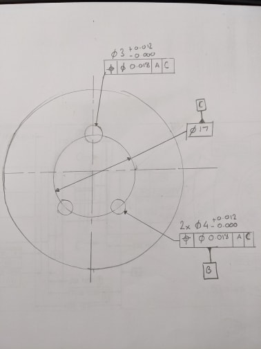
The drawing attached only gives me Datum A and Datum B .

As you can see there are a lot of features to locate and orientate to.

The functionality of the component is Datum B goes against the mating part , with the shaded holes on the right hand side all being dowel hole which locate and orientate that part to the mating component .

Looking at the print and knowing how the part goes against the mating the component .

Could anyone suggest how to best change the drawing to have the correct features as a datum and correctly constrain all 6 degrees of freedom.


Thanks

R
 
Replies continue below

Recommended for you

It sounds like you would want the bolt pattern of the dowel holes to be secondary to B. All 6 DOF would be locked. I don’t understand what A would do if the dowel holes are locating and orienting the part.
 
i totally agree , i am completely confused with the drawing as it it at the moment.

regarding the using the dowel holes as a datum , wouldn't two holes just be sufficient to locate and orientate.

I am struggling to find the best solution to dimension the DRF.

For Example Datum B , would become Datum A then one of the dowel holes datum B then the other datum C ?

I have the ASME 14.5 2018 addition although having a look through it i couldn't find a similar issue .


Thanks

R
 
Two holes would be sufficient for locking down your DOF, but using three would put the axis of the datum on the center of the part and make subsequent dimensioning easier. I don’t have Y14.5 on hand at the moment to find a similar example, but I would call your planar datum feature A (instead of B) and I would call the group of three dowel holes datum B.

I am not a designer, that is just my thought as far as function is concerned. It may be overdimensioned, to your point, by using three datum features as secondary over two.
 
Jacob

In your experience can you actually locate an orientate with 3 dowel holes , I though after two the part would be fixed the 3rd dowel hole would not be needed.

Regarding Eng drawings , should good drawings always have the datums the features that will be used to sit, locate and orientate against the mating part ?


Thanks
R
 
In your experience can you actually locate an orientate with 3 dowel holes, I though after two the part would be fixed the 3rd dowel hole would not be needed.
Two is sufficient for clocking/orientation, but since all three are of equal importance, treat them as a group. That would provide a better match to the function of the part. And as Jacob mentioned, it makes the subsequent dimensioning easier.

Should good drawings always have the datums the features that will be used to sit, locate and orientate against the mating part?
In general, yes... datum features should usually be chosen based on function and how the part engages with adjacent parts. Of course there are exceptions to this, where a non-functional datum feature may need to be chosen.


John-Paul Belanger
Certified Sr. GD&T Professional
Geometric Learning Systems
 
PCD_datum_Rev2_ewl9ii.jpg


Belanger/Jacob


Looking into you guys advice , would the attached drawing be a legitimate way to reference the part.

My thinking the part would locate an orientate from datum A and B .

Although the rest of the features on the part would be positioned to datum C.

Thanks

R
 
The logic in your new drawing appears to be a bit circular. The bolt circle is defined as datum C, yet the holes that make up the circle are positioned to C...

I would call your planar datum A, and I would call the 2x bolt pattern datum B as you have done. Orientation tolerance on B to A (no secondary datum) and possibly a second position segment (no datum) for hole-to-hole position. Then you can position the third smaller hole to A|B.
 
Yes i know , My question , if I use the bolt circle as Datum B , i do not have any orientation control ?

I need to be able to basically square the part up using the two Ø4 dowel holes. Then use the Bolt circle diameter as the center point of which all other features will be positioned to.

The other issue i have the 3 dowel holes have to be very accurately positioned to each other to allow a good fit with the mating part.

I am just struggling to convey this on a drawing.

Any help would be appreciated.

Thanks
R

 
Rwelch9, is there a reason the dowel holes are now of different sizes? Weren't the 3 of them the same size in your initial post? If that is because of what was discussed regarding the rotational degree of freedom constraint (that 2 are enough for), I don't think it's a good enough reason to change the size of one of the holes. Datum feature C seems to be called out incorrectly but that can only be corrected after the decision whether this is a pattern of 3 holes or a pattern of 2 holes and another hole of a different size.
 
Anyway, seems like you may find this figure useful:
Screenshot_20200607-213318_Drive_e9fint.jpg

If the mutual position of the dowel pins to each other is of very high importance, use a composite position tolerance.
 
Burunduk

Yes always been 2x Ø4 and 1x Ø3.

Maybe not the clearest from the initial drawing.

I have queered this with the design engineer to why the use of this 3rd dowel hole is needed. Which i will probably discuss tomorrow.

What would you suggest is the best way to dimension this to ensure there is a very clear and distinctive DRF ?

Right now on the drawing it states the dowel holes have to in position to Datum A, this allows the inspector to orientate that part any way he chooses as there is no clear instructions on the drawing .

This is why i am trying to get it changed and resolved , but finding it difficult to get the drawing correct.

Thanks

Ross

 
It's hard to answer for sure without seeing how the holes are currently dimensioned, and the drawing in the first post of the thread doesn't show that. But if it resembles how you showed it in your last sketch then despite being located on the same pitch circle, the 3 holes are technically not a pattern by the rules of ASME Y14.5, because the number of places does not precede a common specification for the 3 holes, and also because there is probably no simultaneous requirement for them (in your sketch there is but as Jacob noted the choice of datums is problematic) So there is a pattern of two 4 mm holes and another single 3 mm hole.

This is how I would establish the DRF according to the function you described:

* The flat end face is datum feature A (a flatness control should probably be added for it).

* The two 4 mm holes are datum feature B controlled by position to A (controlling orientation and mutual location). See the figure I attached in my previous post for how to designate this pattern as a datum feature.

* The third hole is datum feature C and is controlled by position to |A|B|.

Other features on the part are controlled with reference to |A|B-C|, which means that datum features B and C lock 1 rotation and 2 translation degrees of freedom together and have equal importance.
 
Burunduk

The way you have explained you ideal DRF for my part was excellent.

How do i then still the control of the dowel holes to each other . these must be positional controlled to each other to allow excellent functionality with the mating component.


Thanks


R
 
Rwelch9,

The positional control of the two 4mm dowel holes with reference to datum A ensures both orientation relative to datum A and their location relative to each other.

Controlling the 3mm hole for position with reference to |A|B| with datum feature B being the two 4mm holes ensures orientation relative to A and location relative to those two holes.
 
Right now on the drawing it states the dowel holes have to in position to Datum A, this allows the inspector to orientate that part any way he chooses as there is no clear instructions on the drawing .

If you have 2X 4mm holes positioned to A and 1X 3mm holes positioned to A you would have a simultaneous requirement. They would be considered part of a single pattern, no need to orient one to the other - they are fixed in relative orientation.

The other issue i have the 3 dowel holes have to be very accurately positioned to each other to allow a good fit with the mating part
How do i then still the control of the dowel holes to each other

Simultaneous requirements would fulfill this requirement, and would even be in my mind a better control of relative position than 2X 4mm to |A|, designated datum feature B and then 1X 3mm to |A|B|.
 
Agree with chez311 that if currently the two 4mm holes and the one 3mm hole are controlled by position to A, there is a simultaneous requirement. I missed that part in the post where I said they are not a pattern. With the simultaneous requirement, they are.

I suppose that if you change datum feature A to be the functional end face instead of the non-functional (for interface) cylinder, and you designate the pattern of all 3 holes as a secondary datum feature B, this |A|B| DRF can be another functional solution for constraining 6 degrees of freedom for controls applied on other features on the part.

chez311, do you have a suggestion on how to designate the 2X 4mm plus 1X 3mm pattern as one datum feature in terms of datum feature symbol placement? I think that using "two datum features - single datum" concept for features that are part of the same pattern may not be quite right.
 
I think it would be acceptable to denote the 2X 4mm as B and 1X 3mm as C and reference |A|B-C| as you previously suggested. That is, if its not acceptable to hold other features in simultaneous requirements to A as well, which is also an option.
 
chez311 said:
That is, if its not acceptable to hold other features in simultaneous requirements to A as well
And then just 3 degrees of freedom are constrained (if A is changed to be the flat face). But that is not a problem, because all features that are controlled to A will have to translate and rotate simultaneously in the remaining DOF. I agree that it's another option.
 
if i went for 2x4mm as B and 1x 3mm as C .

Datum B-C would that be the center point of the PCD which would be made up of all 3 holes ?

Thanks

R
 
Status
Not open for further replies.
Back
Top