Continue to Site

Eng-Tips is the largest engineering community on the Internet

Intelligent Work Forums for Engineering Professionals

  • Congratulations KootK on being selected by the Eng-Tips community for having the most helpful posts in the forums last week. Way to Go!

Drawing error ? 1

Status
Not open for further replies.

Rwelch9

Mechanical
Apr 22, 2020
116
Hi guys,

IMG_20200605_223348_trfix9.jpg

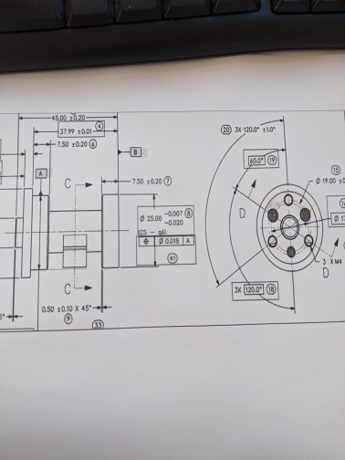
Please see attached drawing from our customer.

The drawing attached only gives me Datum A and Datum B .

As you can see there are a lot of features to locate and orientate to.

The functionality of the component is Datum B goes against the mating part , with the shaded holes on the right hand side all being dowel hole which locate and orientate that part to the mating component .

Looking at the print and knowing how the part goes against the mating the component .

Could anyone suggest how to best change the drawing to have the correct features as a datum and correctly constrain all 6 degrees of freedom.


Thanks

R
 
Replies continue below

Recommended for you

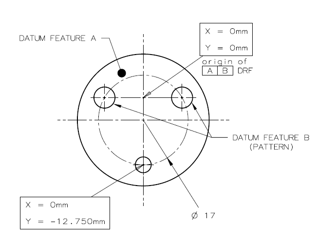
Not a center point datum*. Rather two theoretical planes of the DRF would be implied by default to intersect at right angles to each other and to datum plane A (derived from the flat face), at a location centered between the datum feature simulator pins of the 3 holes. If B-C is specified RMB, this center at which the intersection of planes happens and the DRF axis system is located will indeed coincident with the center of the theoretical pitch circle.

* Point datums are only derived from spherical datum features.
 
Note that this is the default as described in the standard, but the inspector can set the DRF center at any location he likes. The important thing is that the DRF can be used to constrain tolerance zones and set relationships of features to it and therefore to each other.
 
is there anything i could read up on from the 2018 ASME standard ?

just to allow me to understand this a bit clearer.

Thanks

R


IMG_20200610_222150_jsn2f6.jpg


Please see attached rough sketch of what i am taking from your suggestions . Would this an acceptable callout ?

If so would the basic dimensions for Ø25 CF cylinder be 0.0 to B-C ?

Thanks

R
 
I don't have access to the 2018 version but if you look closely at the figure from the 2009 standard I posted in this thread, it can tell you a lot about the DRF establishment in such cases. However, note that the figure shows it for a holes pattern datum feature specified at MMB, therefore the visible looseness between the datum features holes and the datum feature simulators to which the DRF is fixed and as a result some "play" between the part and the DRF (In your case it would allow the DRF to be somewhat movable relative to the center of the pitch circle if that pitch circle is derived from the actual holes and not the pins used as datum feature simulators).
 
Rwelch9 said:
Please see attached rough sketch of what i am taking from your suggestions . Would this an acceptable callout ?

If so would the basic dimensions for Ø25 CF cylinder be 0.0 to B-C ?

Yes, the rough sketch captures the idea.
Your second question - yes, if they are depicted centered in the drawing there is an implied basic zero location.
 
I think my issue with some of this is visual for example , i asked was it the center point of the PCD of holes,

I am thinking 2-dimensional , where looking at your example in previous posts i understand why you referred to planes intersecting.

If for example my dowel holes had a very slight taper on them , this could result in a variation in my DRF.

I will be taking virtual simulators on my CMM.

It is easy to understand for me the center of the PCD of the holes to be 0.0

How does this work with planes to allow Datum B-C to be basic 0.0 for the Ø25 cylinder

Thanks

R
 
Burunduk

One last thing to ensure i am understanding your answers.

the basic dimensions for the 3rd hole ( Datum feature C ) this is position to A+B

This would have a basic of 0, then the dimension between the axis of the hole down to the plane derived from Datum B ?

I work it out in my drawing to 12.75

So a basic of 0 , - 12.75 ?


Thanks

R
 
Rwelch9 said:
If for example my dowel holes had a very slight taper on them , this could result in a variation in my DRF.

Not sure about the effect of the taper, because you have to consider that datum feature A fully constrains 2 rotational degrees of freedom. I can envision how the taper would cause unintentional variation of the DRF if B-C was the primary datum feature (RMB).

Rwelch9 said:
How does this work with planes to allow Datum B-C to be basic 0.0 for the Ø25 cylinder

Think that there is a datum axis derived where the planes intersect. See "datum axis B" in the figure I posted. This could be one of the axes of your DRF coordinate system, setting your basic zero location.

I will try to answer your last question with a sketch later.
 
If for example my dowel holes had a very slight taper on them , this could result in a variation in my DRF.

As Burunduk suggested, as B-C is not primary this is no more a concern than any other type of form/size/orientation error.

It is easy to understand for me the center of the PCD of the holes to be 0.0

How does this work with planes to allow Datum B-C to be basic 0.0 for the Ø25 cylinder

There are certain conventions which the standard suggests about origins of datum planes etc.. These are really less important than your datum feature to datum feature simulator/true geometric counterpart relationship. Your datum planes do not have to be derived in a certain manner to establish particular basic dimensions. As long as your datum features have a basic relationship to each other your measurement origin can be anywhere.

Take for example Y14.5-2009 fig 4-26 that was posted (7 Jun 20 18:36). Convention tells us our origin is in the center of the bolt pattern as suggested by the "means this" portion. But say we specified an origin at the top left hole. Or the top right hole. Or anywhere else. Do you expect the simulation requirements or effect on subsequent tolerances to change? No - because the datum feature and simulator relationship did not change.
 
chez311 said:
There are certain conventions which the standard suggests about origins of datum planes etc.. These are really less important than your datum feature to datum feature simulator/true geometric counterpart relationship. Your datum planes do not have to be derived in a certain manner to establish particular basic dimensions. As long as your datum features have a basic relationship to each other your measurement origin can be anywhere.

I agree.

Rwelch9, what chez311 explained further clarifies the idea in my post from 10 Jun 20 21:17 above.
 
Status
Not open for further replies.

Part and Inventory Search

Sponsor