Eng-Tips is the largest engineering community on the Internet

Intelligent Work Forums for Engineering Professionals

Drawing Like That

Status
Not open for further replies.

Sazirul

Electrical
Aug 5, 2017
32
0
0
BD
Hi,

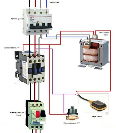
Can anyone tell me, what is the mane of this type of drawing and how can I create one like this? I just have Autocad Electrical 2015. Can I do it by Autocad Electrical?

2019-04-06_111829_efe59z.jpg


Thanks!

Electrical Isolator | Busbar VS Cables | Engineering Root
 
Replies continue below

Recommended for you

"Pictorial Wiring Diagram", if you like.

I don't know if these sorts of pictorial diagrams are covered by any formal standard that would mandate a formally-agreed nomenclature.

So you can call it whatever you want within reason. Unless somebody can point to an applicable standard that defines a name, it's merely opinion.

And of course one needs to extract images from typically-PDF spec sheets or catalogs. Then spend a few minutes erasing the background, and copying with the transparent option. Or set-up a white background and take photos of actual hardware.

When used to describe a system, then they might be called a Pictorial Block Diagram. Difference is the wires are replaced with signal and power paths.

 
That is correct, Visio does not have pictorials of equipment, although it does have line drawings of some things. The main advantage of Visio is that it's a vector-based drawing, so you can move things around without redrawing everything

TTFN (ta ta for now)
I can do absolutely anything. I'm an expert! faq731-376 forum1529 Entire Forum list
 
IRStuuf:
It is not clear from the Visio web sites that I have seen. Can I use Visia to make accurate vector-based line diagrams? That is, can Visio draw a ray 13.25 units long at 5.75 degrees from horizontal? A second ray (arrow shape) 6.75 units long at 12.52 degrees from the horizontal?
 
Yes, it can; it's basically a 2D CAD drawing program with pretensions of being a schematic capture program. You can add connection points to anything, including bitmap images like those above and connect "wires" between them. When you move the bitmaps around, the lines would follow along and try to rearrange themselves to deconflict. I've drawn satellite orbits to determine angles of incidence on the ground, etc., as well as layouts of multichip modules. Visio has a basic precision of 4 decimal places and maintains its own unit system allowing you to specify in inches, say, and get measurements in km, etc., as well as measuring and setting angles, so you can rotate any shape, including bitmaps in 4 decimals of precision and measure same.

Visio_rr1szr.png


TTFN (ta ta for now)
I can do absolutely anything. I'm an expert! faq731-376 forum1529 Entire Forum list
 
Like others, I would create that diagram in Visio. No need to find a library, especially if this is for internal use, just use Google image search and you can usually find the images you need.
asdf_ohzuhh.png
 
That is known as a “3D point to point wiring diagram”, it’s a relatively new feature in AutoCAD (Autodesk) Electrical software packages. In the AutoCAD version they don’t use photos of actual devices like that, they are more generic graphical representations, but control equipment mfrs will substitute the generic images with images of their own devices as a form of promotion (or from their perspective, “clarity”).

I can imagine a day coming in the near future when technicians will no longer be capable of reading a schematic... maybe we are already there.


" We are all here on earth to help others; what on earth the others are here for I don't know." -- W. H. Auden
 
Status
Not open for further replies.
Back
Top