Continue to Site

Eng-Tips is the largest engineering community on the Internet

Intelligent Work Forums for Engineering Professionals

  • Congratulations SDETERS on being selected by the Eng-Tips community for having the most helpful posts in the forums last week. Way to Go!

dv/dt filters or sinus filters for motor with cable length of 60 meters/200 ft? 9

Status
Not open for further replies.

edison123

Electrical
Oct 23, 2002
4,501
Cage motor is rated for 575 V, 366 A, 4 pole and runs at 25 to 40 Hz.

Siemens VFD model 6SE7238-6FS00-3AD0-Z has a front end filter on the input side and a RL90003 Reactor on the output side.

The motor cable length is 60 meters/200 ft and there have been many stator winding failures due to turn shorts leading to ground fault. All the original and rewinds are with VFD duty rated class 180 deg C magnet wire and class 200 deg C rated aramid paper ground insulation.

Are dv/dt filters or sinus filters at the VFD output needed to prevent the stator winding failures with the 60 meters/200 ft motor cable?

Muthu
 
Replies continue below

Recommended for you

1. Are you positive the failure mechanism is "turn-to-turn" short and not "phase-to-phase" or "phase -to-ground"?
2. High temperature insulation systems tell you nothing about its ability to handle the rapid voltage transients and peak voltage conditions resulting from VFD operation.
3. If you do have turn-turn shorts: is it in the end (outside the slot) region or within the slot portion?
4. If strand insulation is solely enamel, it is fairly easy to "nick" it as the coil is formed. This can happen from simple handling (either from a burr on the winding tool when making the coil itself, or when inserting the coil into the slot), or from imperfections during manufacture - for example before spooling the material onto the reel).

If you are seeing actual turn-turn faults (and not something else), then there are two basic options.
A) Pass it off on the motor design and increase the turn-turn voltage capability of the winding by using dedicated turn insulation (or extra phase insulation, if the fault is actually phase-phase).
B) Pass it off on the drive performance and use filters or other means to limit BOTH the rate-of-change of voltage AND the peak voltage(s) seen by the winding. Note that this second approach may also require investigation of common mode voltage effects.

Converting energy to motion for more than half a century
 
The failures started as turn to turn shorts and developed into a ground fault near slot exit area, where there is sufficient space between adjacent coils and hence phase to phase fault is ruled out.

All the insulation materials from magnet enamel to slot insulation are rated for both VFD duty and temperature class. No further space to add turn to turn insulation.

5 OEM windings (VPI) in 3 different client sites have failed within a year and 2 rewound windings (non-VPI) failed within a year. 3 rewound motors are in service for more than a year.

The rewound motors were surge tested at 6 KV for both individual coils and phase to phase. The AC HV test was done at 6 KV phase to phase+ground. These are extreme levels of testing for a 575 V motor, which the windings had passed successfully with zero failures at shop and yet they failed at site within a year.

Hence, my doubts about the drives and if additional filter (dv/dt or sinusoidal), instead of just a reactor, at the VFD output is needed to protect these motors with 200 ft cable length.

Muthu
 
Is it a mush winding? That can have issues with starting and ending turns too close together.

An extra filter could definitely help. Be careful because some sinusoidal filters add common mode voltage.
 
Is there a photo of the failed winding region? And is there a description of the driven process (e.g., fan, compressor, pump, extruder, conveyor, etc.) and motor orientation (vertical vs horizontal)?

Two things about your testing. A hipot is a "coil to ground" test, determining the insulating ability of the ground wall insulation. It can tell you nothing about a phase-to-phase or turn-to-turn fault, unless it occurs in conjunction with a ground fault. A surge test, if performed properly, compares the response of different phases but does not test "phase to phase". It tests turn-to-turn. The strenuousness of both types of test are critically dependent on the rise time and the peak value of the applied AC waveform.

I see the failure mode happen occasionally for a number of reasons, but the primary ones related to motor design / winding are:
A) Phase paper (and/or dedicated turn insulation) is not seated close enough to the end of the slot to prohibit contact between turns. Over time, the coils will move relative to each other as a result of process-induced vibration effects and/or starting transients. If unlucky, the insulation will break down, allowing the energy from the switching transients caused by the drive to catastrophically fail the winding at the specific point mentioned. Most often, this is a result of improperly trained winders (they don't know why having the paper there is important), or lazy ones (it takes work to get that insulation in there early in the coil-laying process, and it gets harder with more coils added).
B) The exposed winding is acquiring some sort of contaminant, leading to a tracking path (over the outside of the insulation) - which will eventually cause grief as a short-to-something somewhere. The abruptness of the rise time and the amplitude of the voltage peak during the switching transients will make things appear worse. Be aware of possible reflected wave syndrome due to the cable length, as well as the effect of common mode voltage.
C) A "bad batch" of wire (cracked / chipped / scratched enamel) and/or a slot burr right at the edge of the slot creates an abrasive region and the relative movement of the coil eventually fails the insulation. Note that some OEMs are more prone to this type of failure mechanism compared to others. Can be fixed with the same approach as A) - time, effort, and training of the individuals winding the machines.

Another thought: are there multiple drives (of the same or different rating) on the same bus? Are some (or all) of them having the same issue? It might not be a "bad drive", it might be "bad input waveform".

Converting energy to motion for more than half a century
 
OP said:
motor cable length is 60 meters/200 ft
This is in the region I would expect a possibility of resonance.

To be sure this a your problem measure, waveform at the motor terminals. See this
This vendor has set up a model that should be able to simulate the impact of a drive output filter with 50m long cable.
Some filter parameters make the resonance worse, dv/dt filters need to be selected for your situation.
AFTER you are sure this is your problem, and not the manufacturing problems discussed above.
 
Lionel

Yes, all these are mush winding motors and start and end turns could be together. Thanks for confirming an extra filter would help.

Gr8blu

This motor drives an off-shore oil drill. When we Hipot one phase, the other two phases are grounded thus testing phase to ground and phase to phase at the same time. The end winding phase to phase Nomex separators are there going up to the slot neck. This is not a TEFC motor. An external blower throws the surrounding air at the top vent and the hot air exits through bottom vents of the motor. Since this motor is on off-shore platform, salty moisture is a reality.These motors have failed at 3 different sites so supply system could not be an issue. Apparently, the inverter has two output sections and two motors are run from the same VFD in master/slave mode.


FacEngrPE

Will ask the client to do the experiment along with the VFD supplier.

Muthu
 
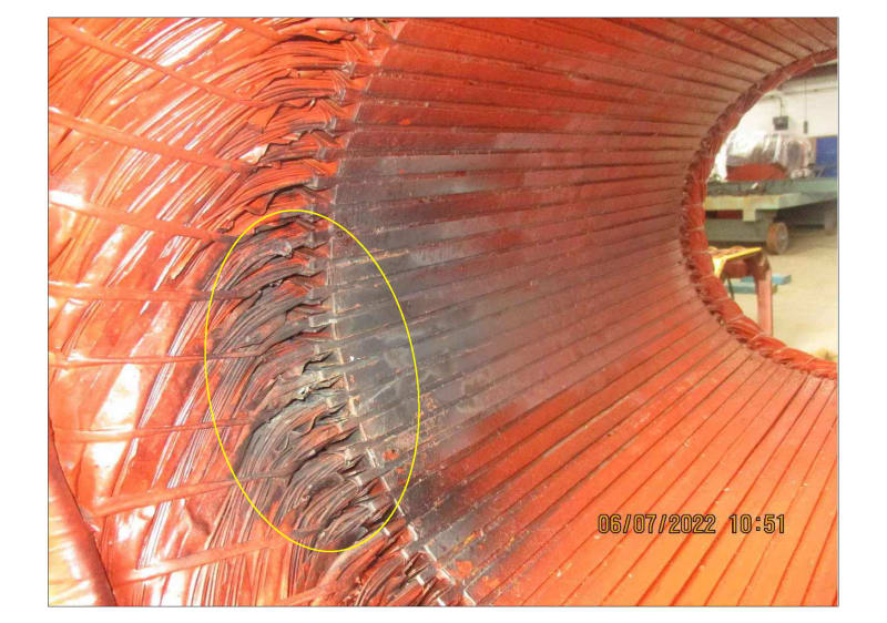
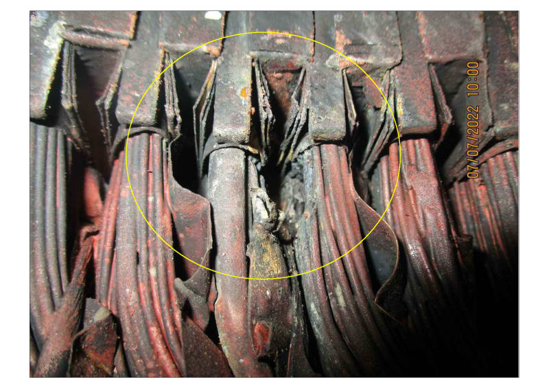
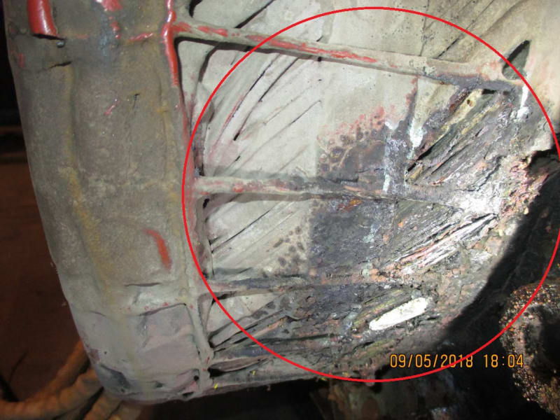
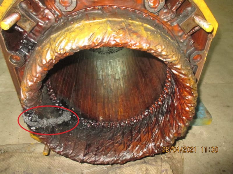
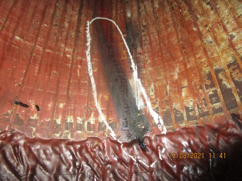
Winding failure photos

02_ekugbp.jpg


03_bhyt9t.jpg


Muthu
 
2 motors run from one VFD would not be a Master/Slave application, it's just two motors. I suppose you have separate OL protection for each motor? But by "master/slave", I hope you don't mean that they use the drive to start one motor, then pull the other in after the first is at speed using a contactor. THAT would be a really bad idea (but more for the VFD, not the motor).I will say however that two motors on one drive increases the possibility of resonance in the output circuits.

The photos are not clear evidence of it being an issue from voltage pulse damage to the windings. It might be, or it might be something else. Looking at the EASA winding damage photos it tracks as a possible voltage surge OR contaminants, vibration etc. Given the environment and what appears to be signs of corrosion, I might suspect the salt air as a possible culprit.

Are the drills off-line for extended periods of time? If so, you might consider motor heaters to prevent them from cooling down enough to allow for condensation to form when not in use. Since you have a VFD, check to see if it has a motor winding heat functionality available in it.

I would not waste money on a sine wave (sinus) filter for something that short, but when you have remote installations, a dV/dt filter would not be a bad idea for this and several other reasons.


" We are all here on earth to help others; what on earth the others are here for I don't know." -- W. H. Auden
 
Thanks, jeff.

It's a tandem setup where two motors drive the same gearbox which drives the vertical drill. May be they mean master/slave in terms of speed synch between the two output inverter sections? You still think resonance could be an issue?

They all have space heaters which come on when the VFD power is cut off. Not sure if they use VFD to warm up the motor.

Below are a few OEM VPI winding failures which indicate high voltage resulting in turn to turn faults and ground faults. They failed at 3 different client off-shore rigs.

I will tell my clients to install dv/dt filters to protect their motors and my warranty.

1_jj5cc5.jpg


3_fuwzr6.jpg


4_k4u1f4.jpg


Muthu
 
jeff

What would be the cost of retrofitting a dv/dt filter to existing VFD for this capacity?

Or it would be better to go for a new VFD with the filters in-built?

Muthu
 
You can get stand-alone enclosed dV/dt filters, they don’t need to be built into the VFD. No idea on the costs though, I’ve been removed from the economic aspects of things for too long now.


" We are all here on earth to help others; what on earth the others are here for I don't know." -- W. H. Auden
 
Thanks, jeff. Two clients have told that they will look into retrofit of dv/dt filters. Motor failures in off-shore rigs is a big pita for everyone considering the logistics and production loss.

Muthu
 
May try to reduce drive pulse frequency, at least till a dv/dt filter will be installed.
 
Yes, most VFD allow to select pulse/switching frequency, some has a setting to automatically reduce pulse frequency vs temperature module/heatsink.
This may help to avoid some (close) resonance and ringing in circuit VFD-cable-motor.
Ideally, check voltage spikes at motor leads vs modifing pulse frequency - - difficult to do at operation site.
Rising time of switching devices is fixed (by hw driver and device itself) so to reduce dv/dt effect only a dv/dt filter may help.
60m cable mean high risk for dv/dt effect even it's about a high power motor that has low impedance and this may reduce dv/dt effect.
 
Be aware that some drive mfrs refer to the pulse frequency as the “carrier frequency”, others refer to it as the “PWM frequency”, etc. Another thing that some do is to lock it into “Advanced Parameters” requiring an access code to be able to access them. So sometimes it takes some sleuthing to find it in the programming instructions. What brand / model of drive is it?

If your carrier frequency is already down to around 1.2kHZ, that’s usually as low as they go. But often times people will have increased it to attempt to make the motor “quieter”, which really just moves the sound out of the range of human hearing (but it will drive your dog insane). Unfortunately many people do this without understanding the full consequences.


" We are all here on earth to help others; what on earth the others are here for I don't know." -- W. H. Auden
 
Thank you, iop and jeff.

It's Siemens VFD model 6SE7238-6FS00-3AD0-Z with a front end filter on the input side and a RL90003 Reactor on the output side per clients.

I will ask the clients to discuss with their VFD/motor supplier to see if the carrier frequency can be altered.

Muthu
 
@edison,
I tried to focus on the operating range of your VFD 25 to 40 Hz). Have you tried making vibration measurements at the different operating frequencies? We had a series of failures before where the resolution was just skipping a frequency range where the motor inductance and the filter capacitance resonated. Please see your VFD manual if frequency skipping is possible when you shall have noticed resonance at a specific frequency range.
 
Status
Not open for further replies.

Part and Inventory Search

Sponsor