Eng-Tips is the largest engineering community on the Internet

Intelligent Work Forums for Engineering Professionals

  • Congratulations waross on being selected by the Tek-Tips community for having the most helpful posts in the forums last week. Way to Go!

Dy11 TX not connected RYB to ABC 3

Status
Not open for further replies.

arrow123

Electrical
Jan 13, 2004
13
0
0
NZ
Hi
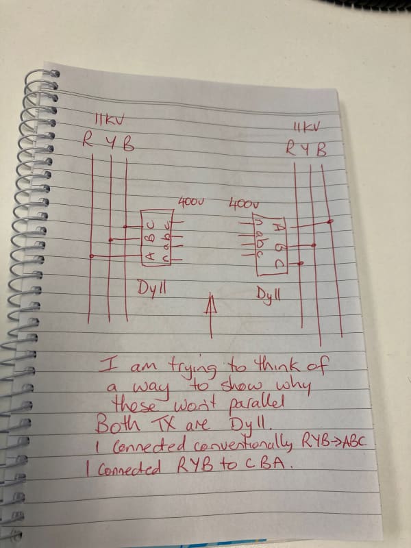
We have a few situations where 11kV/400v TX's are put up poles that have their ABC terminals connected to BYR phases in that order so won't parallel with the next transformer down the line that has been put up the conventional way of connecting RYB to ABC. (The Tx's have been fitted up poles n opposite sides of poles) Does anyone have a quick method of drawing this out either with vector diagrams or simple analogies to explain why it won't parallel. Thanks
 
Replies continue below

Recommended for you

See faq238-1154.
Not the exact question, but you might be able to adapt the method.

You cannot fix this with connections on the wye side.
 
Thanks Beyond86 - both Transformers are Dy11. I am waiting for the exact voltages between the Transformer secondaries but we do know they won't parallel. We have had this in other parts of the network and I just can't think of a way to prove it graphically why it won't parallel.

Thanks stevenal - I couldn't get the document to open here so will try it from home in case there is a block on opening files etc.
I have added a photo of a drawing showing what I was trying to describe, but just can't think of how to draw it out vectorially or some other way.


TX_connections_iyyala.jpg
 
Darn, engineering.com broke my link.

Update: I edited the first link so it now points to the same file now found elsewhere. The second link was to my own sketch illustrating the steps. You may be able to follow the steps without it. I used ABC for the conductor designations and H123, X0123 for the transformer bushings. Adjust as needed.
 
The case you have mentioned is
1) RYB sequence to RYB terminals of Dyn11 transformer. This means standard phase seq is given to a transformer with standard polarity. Pl. refer to Fig a.
2) BYR sequence to RYB terminals of Dyn11 transformer. This means reverse phase seq is given to a transformer with standard polarity. Pl. refer to Fig d.
You will find a 120deg phase difference between a1a2, b1b2, c1c2.
[URL unfurl="true"]https://res.cloudinary.com/engineering-com/image/upload/v1621049979/tips/IMG-5317_r2qkoy.pdf[/url]
 
Forget about a to a, b to b, and c to c...
Think about rotation and displacement.
Let’s say RYB is ABC rotation. That is, B follows A, and C follows B.
You connect it to the XF with R to H1, (which I’m assuming you are calling A on the XF)
Y to H2, and B to H3. On your nameplate it will look exactly as shown with the secondary lagging the primary by 30 degrees.(or high side leading low side by 30 degrees)

Now, take the exact same transformer as you have done and connect it as you have. That is, R to H3, Y to H2, and B to H1. The nameplate drawing is now a “mirror” image. You are now “rotating” through the transformer backwards, which when drawn out shows you now have the secondary leading the primary by 30 degrees. (Or high side lagging the low side by 30 degrees) IA+ic=ia. IA=ia-ic

When you try to parallel these two transformers on the secondary side, (swap the a & c wires on one XF to try to match rotation), you will find there is a 60 degree difference in the voltages.

That’s where the 120 and 60 degree disagreement is coming from in these posts.

You can fix rotation on the secondary side by swapping wires to parallel. You have to swap wires on the primary side to fix displacement issues.
 
Thank you all very much.
Thats all great info, makes sense to me, I was struggling to work out how to show it. Much appreciated
 
Status
Not open for further replies.
Back
Top