MGutarra
Structural
- Jan 12, 2020
- 3
Hello there:
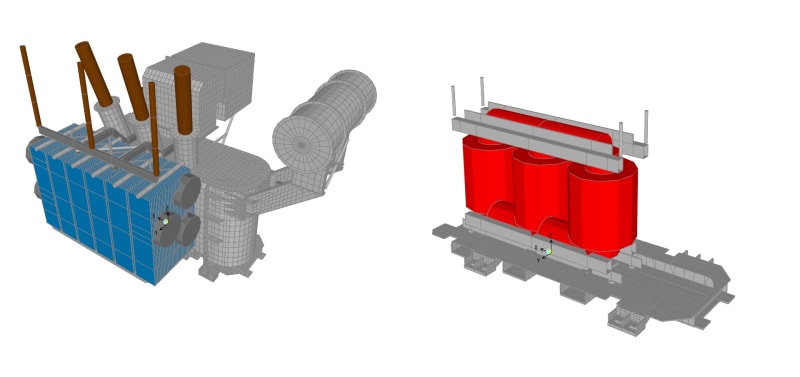
So basically, according to IEEE 693, I need to perform a dynamic analysis of a transformer-bushing system using FEA. I've done static analysis of these machines before but this is the first time I have to make a FEA of a transformer. The concept seems to be simple: model the ''structure'' and obtain the mass participating ratios and natural frecuencies, that is all I need. The problem I have is im not sure how to model this machine, I've seen some papers showing pictures like the one I attached, but it's not clear to me the nature of the modelling. Are those shells all the model? is it only the case being modelled with all the mass distributed in the exterior shells? Or are they modelling the interior parts of the machine too? How are the masses distribuited in these kind of models? What elements are considered in the stiffness of the model and what elements are considered only as ''loads'' for mass porpuses? If someone has experience with these kind of modelling, I would really appreciate their help.
Thanks in advance.
Link with model example:
Disclaimer: I posted this in the FEA section but no one answered and I really don't have much time left. Hope this doesn't upset any moderators. This section seems to be more active.
![[idea]](/data/assets/smilies/idea.gif "[idea] [idea]")
