GRADSTRUCT
Structural
Hi All,
I know similar topics have been discussed a lot here, and I've tried my best reading and understanding these threads to understand the intent of the different WALL/COLUMN design clauses in these codes. Could someone please let me know if my understanding on how to design a less than 4 Storey building is correct or make any suggestions? Also disclaimer, I'm not trying to find a loophole in the code to reduce my reo/tie requirements - this is just my understanding of the clauses.
For Context, I use Inducta - RCB to do my lateral analysis.
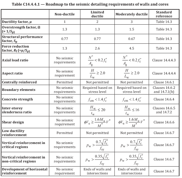
1) First, I model the full structure with only my shear walls and core walls fixed-fixed with everything else pinned-pinned. Based on this analysis (with ductility factor 1), I check my horizontal displacement, the shear, moment and axial capacity of the shear/core walls ONLY. If all okay, I proceed with ductility factor 1. Or else, I increase to ductility factor 2, check if axial stress in these walls are less 0.2f'c, and add the necessary boundary elements for my shear walls.
2) Then, I re run the model (with ductility factor 1) with all my other vertical load bearing elements as fixed-fixed and design my columns for these conservative forces. And all my blade walls I check if any of them have tension in any section by checking P/A +- M/Z. If any of them are in tension I design them as columns and see if I can get them to work with only mesh both face. By keeping f'c < 50MPa and my vertical reo ratio < 0.01Ag I could get away with the tie requirements. The rest of the blade walls I design to simplified method in Sec 11.
3) In the end, I would have designed the shear walls for ductility factor 2 forces (in plane shear capacity of these walls to ductility factor = 1) with additional detailing for ductility. Columns as fixed-fixed for ductility factor 1 or 2 forces. Blade walls in Tension as Columns with only mesh with ductility factor 1 forces. Blade walls in Compression also with only mesh with ductility factor 1 forces. Also any squat walls (one storey walls) as only mesh with ductility factor 1 forces.
Is this correct? If I model every column and blade wall as fixed-fixed, my design would end up being very conservative. If my columns and blade walls are precast and I only have a dowel connection, I'm essentially forcing these vertical elements to be pinned-pinned right?
Thanks in Advance for your comments and suggestions.
I know similar topics have been discussed a lot here, and I've tried my best reading and understanding these threads to understand the intent of the different WALL/COLUMN design clauses in these codes. Could someone please let me know if my understanding on how to design a less than 4 Storey building is correct or make any suggestions? Also disclaimer, I'm not trying to find a loophole in the code to reduce my reo/tie requirements - this is just my understanding of the clauses.
For Context, I use Inducta - RCB to do my lateral analysis.
1) First, I model the full structure with only my shear walls and core walls fixed-fixed with everything else pinned-pinned. Based on this analysis (with ductility factor 1), I check my horizontal displacement, the shear, moment and axial capacity of the shear/core walls ONLY. If all okay, I proceed with ductility factor 1. Or else, I increase to ductility factor 2, check if axial stress in these walls are less 0.2f'c, and add the necessary boundary elements for my shear walls.
2) Then, I re run the model (with ductility factor 1) with all my other vertical load bearing elements as fixed-fixed and design my columns for these conservative forces. And all my blade walls I check if any of them have tension in any section by checking P/A +- M/Z. If any of them are in tension I design them as columns and see if I can get them to work with only mesh both face. By keeping f'c < 50MPa and my vertical reo ratio < 0.01Ag I could get away with the tie requirements. The rest of the blade walls I design to simplified method in Sec 11.
3) In the end, I would have designed the shear walls for ductility factor 2 forces (in plane shear capacity of these walls to ductility factor = 1) with additional detailing for ductility. Columns as fixed-fixed for ductility factor 1 or 2 forces. Blade walls in Tension as Columns with only mesh with ductility factor 1 forces. Blade walls in Compression also with only mesh with ductility factor 1 forces. Also any squat walls (one storey walls) as only mesh with ductility factor 1 forces.
Is this correct? If I model every column and blade wall as fixed-fixed, my design would end up being very conservative. If my columns and blade walls are precast and I only have a dowel connection, I'm essentially forcing these vertical elements to be pinned-pinned right?
Thanks in Advance for your comments and suggestions.