Continue to Site

Eng-Tips is the largest engineering community on the Internet

Intelligent Work Forums for Engineering Professionals

  • Congratulations GregLocock on being selected by the Eng-Tips community for having the most helpful posts in the forums last week. Way to Go!

Eccentrically Loaded area supported on 4 piers 1

Status
Not open for further replies.

Pete1919

Structural
Dec 4, 2015
14
Hello all,
I need help please. I have 6'(say, x-axis) x 4'(Y-axis) area with a point load of 100 tons acting 2' from short neutral axis (ex = 2') and 1' from long neutral axis (ey=1). The area will be supported on four (4) piers. What will be the load distribution on 4 piers? Weight of the pad (area) will be ignored.

I calculated moment and calculated stresses at 4 corners using p/A+/-Mx/Ix*y +/-My/Iy*x. I interpolated stresses at mid-points between corners. Stress at center would be 100/24=4.17 tsf. Then I assigned tributary areas (four quadrants) to each pier. Took "average" stress for the quadrants multiplied by quadrant area of 6 sq.ft to get pier loads. The pier loads were 69, 31, -19 and 19 tons.

Using different method of 25+/-My/(6*2) +/- Mx/(4*2), I came up with the pier loads of 54, 29, -4, and 21 tons.

I am trying to find which method and answer is correct. Any comments or calculation will be appreciated. Thanks.
 
Replies continue below

Recommended for you

hokie66 said:
Try summing the moments about a corner.

P/A + Mc/I has been my go to method as well so this caught my eye. I checked other hokie's method for moment balance about all four corners using three different axes (0,90,45) and a square footing (so I could do it in my head). All good.

hokie66 said:
If I am distributing the forces incorrectly, I would like someone to explain why.

Strain compatibility. Modelled with a rigid cap and all piles modelled as axial springs having equal, bi-directional stiffness, I do not believe that your solution would satisfy strain compatibility. When the loaded corner depresses, the cap rotates and the other corners displace as well. As such, they draw load.

That said, if you provided 100% capacity at the the one, loaded corner, I doubt that you'd be in any real world trouble. Cap flexibility and reduced pile tension stiffness would shift things closer to that distribution anyhow.

I like to debate structural engineering theory -- a lot. If I challenge you on something, know that I'm doing so because I respect your opinion enough to either change it or adopt it.
 
OK, so Hokie93's numbers are in static equilibrium. But you can change those numbers, just keeping the tabletop balanced about the diagonal. So there is apparently not a unique solution using that method.

We know nothing about the stiffness of the cap or the flexibility of the supports. My calculation assumed rigidity, not springs.
 
hokie66 said:
We know nothing about the stiffness of the cap or the flexibility of the supports. My calculation assumed rigidity, not springs.

With four available external reactions and two applicable statements of equilibrium, it seems to me that this problem is statically indeterminate. As such, resolution can only be brought about by giving consideration to flexibility somewhere in the system. In the conventional presentation of the P/A + Mc/I method, that flexibility is assigned to the axial behavior of the piles. Once that is done, and strain compatibility is enforced, I believe that a unique solution is available.

hokie66 said:
But you can change those numbers, just keeping the tabletop balanced about the diagonal. So there is apparently not a unique solution using that method.

Would you be willing to throw out an example that I could tinker with?

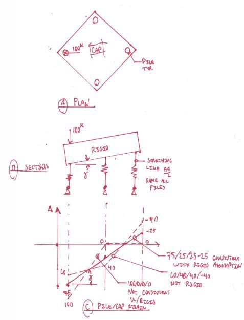
Consider the case where all 100 kip is applied over one pile as you've suggested. Now draw a diagonal section through the cap from the loaded corner to the opposite corner. In that section, the cap (assumed rigid) will have a slope to it, right? If so, then at least two of the piles must have non-zero vertical displacements and therefore non-zero reactions. In my opinion, that makes the 100/0/0/0 solution inadmissible.

I like to debate structural engineering theory -- a lot. If I challenge you on something, know that I'm doing so because I respect your opinion enough to either change it or adopt it.
 
When we do analysis of continuous concrete beams in structures, we normally don't allow for support settlement. And a column load from above does not affect the load on remote columns. Now this simplified analysis does not apply in high rise buildings, but I think here we are just talking about a simple case where everything is assumed to be infinitely stiff.
 
In a statically indeterminate system, which I believe this to be, the whole concept of load distribution becomes meaningless if all things are rigid. There's just nowhere to go analytically.

The continuous beam / support settlement issue can be viewed at least two different ways. One is to assume that there is no support settlement; the other is to assume that there is uniform support settlement. The answers will be identical but the latter assumption will be much more correct conceptually. As such, I see no rigid supports, just uniformly flexible ones and non-uniformly flexible ones.

I like to debate structural engineering theory -- a lot. If I challenge you on something, know that I'm doing so because I respect your opinion enough to either change it or adopt it.
 
So do you agree that 100 tons applied directly over the corner support results in a 75 ton reaction?
 
Without knowing the dimensions and length of the piers, it is impossible to calculate any shortening effect in the supports, so the only assumption that can be made is that the supports are rigid axially.

In that case, if the load is applied directly over one support, then that support must take 100% as Hokie66 suggests.

The only way that load can distribute to the other supports is if shortening is allowed for in the supports, which is not possible to calculate without defining the properties of the supports either as springs or members with all of the normal properties plus lengths.

Yes, conceptually, there will normally be shortening in the supports, but how much depends on the missing data, so we cannot allow for it and cannot calculate its effects on distribution of load to other piers. The only concept we can logically consider is no shortening in the supports!
 
Hokie said:
So do you agree that 100 tons applied directly over the corner support results in a 75 ton reaction?

I do. I worked through it algebraically and it turns out that, abiding by the assumptions of other Hokie's/my proposed method, that same distribution would apply to any rectangular pile layout.

raot said:
Without knowing the dimensions and length of the piers, it is impossible to calculate any shortening effect in the supports, so the only assumption that can be made is that the supports are rigid axially.

Another, more realistic assumption that can be made is that all of the piles posses equal axial flexibility/stiffness. And indeed, that is precisely the assumption that underpins the P/A + Mc/I method.

rapt said:
The only concept we can logically consider is no shortening in the supports!

As I demonstrated above, the rigid support assumption is not an admissible solution from a strain compatibility perspective so long as the very common rigid cap assumption is at play:

KootK said:
Consider the case where all 100 kip is applied over one pile as you've suggested. Now draw a diagonal section through the cap from the loaded corner to the opposite corner. In that section, the cap (assumed rigid) will have a slope to it, right? If so, then at least two of the piles must have non-zero vertical displacements and therefore non-zero reactions. In my opinion, that makes the 100/0/0/0 solution inadmissible.

I like to debate structural engineering theory -- a lot. If I challenge you on something, know that I'm doing so because I respect your opinion enough to either change it or adopt it.
 
The last part about my solution being inadmissible is astounding to me. But then I don't accept that the cap would have a slope. Even if it did, how much slope? Why would not the degree of the slope affect the reactions?
 
KootK,
Sorry, I missed one thing you asked for. 7 Dec 2109 you asked for another solution similar to Hokie93's, as I said it was not unique.

Try 70/30/30/-30. Or 80/20/20/-20. Or 100/0/0/0.
 
hokie66 said:
The last part about my solution being inadmissible is astounding to me.

Well, before I go all David Copperfield on this, let's keep in mind that it's only inadmissible in a strain compatibility sense given a particular set of assumptions. I've no doubt that your solution is perfectly acceptable as a real world solution. In fact, if I was designing such a system, I would probably go Hokie66 for the pile under the load and Hokie93 for the other piles and the cap. Maybe a little more Hokie66 for direct bearing checks over the loaded pile.

Hokie66 said:
But then I don't accept that the cap would have a slope. Even if it did, how much slope? Why would not the degree of the slope affect the reactions?

Fortunately, for the P/A + Mc/I analysis, you don't actually need to know the slope. You only need to generate a solution where the pile strains would be consistent with a constant slope of some magnitude across the underside of the cap. The slope definitely would affect the reactions. That's part of the method. All this is similar to how one would calculate stress in a beam without actually knowing the curvature explicitly.

Hokie66 said:
Try 70/30/30/-30. Or 80/20/20/-20. Or 100/0/0/0.

Thanks for this. In the sketch below I plotted 60/40/40/-40 instead so as to exacerbate the difference between that and the other solutions graphically. My argument is that, because the piles strains do not lie on a straight line, the solution is not consistent with strain compatibility (assuming rigid cap and equally stiff piles). Kinks in the graph suggest non-rigidity in the cap. Similar logic would apply to the two bonus solutions that you supplied.

Capture_k5bdyg.jpg

I like to debate structural engineering theory -- a lot. If I challenge you on something, know that I'm doing so because I respect your opinion enough to either change it or adopt it.
 
A neat piece of work, but all it tells me is that the method proposed seeks a triangular stress distribution, similar to an eccentrically loaded footing on soil. I don't find that logic applicable to piles, and neither would I use it for soil with a load at the edge.
 
Kootk,

Ok, I was looking at it from a purely analysis perspective.

I can see what you are doing but it relies on
- the pile cap being rigid.
- all piles being the same length and founded in exactly the same material. Reasonable assumptions at design time but they would have to be confirmed on site depending on the slope of any geological features etc.
- And the tension response of the piles is exactly the same as the compression response for the piles, which I would doubt even at design time as compression is probably dominated by end bearing while tension would be purely skin friction.
 
rapt said:
I can see what you are doing but it relies on...

Yep, made most of those same points myself along the way:

KootK said:
That said, if you provided 100% capacity at the the one, loaded corner, I doubt that you'd be in any real world trouble. Cap flexibility and reduced pile tension stiffness would shift things closer to that distribution anyhow.

Where I practice, foundation design tends to be a fairly crude affair. We use conservative loads and don't lose a lot of sleep over accuracy in analysis.

While I ascribe to the Mc/I method, I feel compelled to point out that it's not my method. It shows up in locally popular foundation texts and seems to be the way of things in Canada and the U.S. from what I've seen. Think of me as merely your friendly tour guide to the Mc/I + P/A method. Like Gilligan.


I like to debate structural engineering theory -- a lot. If I challenge you on something, know that I'm doing so because I respect your opinion enough to either change it or adopt it.
 
hokie66 said:
A neat piece of work, but all it tells me is that the method proposed seeks a triangular stress distribution, similar to an eccentrically loaded footing on soil.

Well yeah, we're not splitting atoms here. That said, the rigid cap pile strain gradient concept provides the answers to several of your inquiries here:

- why the Mc/I crowd has been challenging your load distribution.
- why I've been harping about strain compatibility inadmissibility.
- the effect of cap slope on pile reactions.
- the existence of a unique Mc/I solution.

Your welcome.

In exchange, perhaps you would consider elaborating on why you reject the Mc/I method?

I like to debate structural engineering theory -- a lot. If I challenge you on something, know that I'm doing so because I respect your opinion enough to either change it or adopt it.
 
Dear, dear, why do I get involved in these?

Anyway, I did manipulate the numbers, not without some difficulty, as others above experienced.

With the OP's problem, the P/A +/- Mc/I approach gives 54, 29, -4, 21, as Pete got by one method, as verified by njlutzwe and Hokie93.
My answers, using simple beam theory in each direction 62, 21, 4, 13.

As to the full load directly on the corner, I also got the 75, 25, etc. answers using your approach. I haven't rejected it, but haven't accepted it either. Goes against the grain to distribute a portion of an edge load inward by bending of the pile cap, when it can go straight down in compression. If the piles were inset with the load outboard, then bending of the cap is good.

Can anybody cite a text reference?
 
The P/A + Mc/I load distribution method is covered in the following texts/manuals and probably many others.

1.) "Foundation Engineering" (Second Edition) by Peck, Hanson, and Thornburn.
2.) "Foundation Analysis and Design" (Fourth Edition) by Joseph E. Bowles.
3.) "Design of Concrete Structures" (14th edition) by Nilson, Darwin, and Dolan.
4.) "Structural Engineering Handbook" (Third Edition) by Gaylord and Gaylord.
5.) CRSI "Design Guide for Pile Caps" (First Edition, 2015)


@Hokie93: nice work with references. Saved me some work there.

hokie66 said:
Goes against the grain to distribute a portion of an edge load inward by bending of the pile cap, when it can go straight down in compression.

Agreed. The more direct load path is usually the better load path. The only time that I'd provide less than 100% capacity right under the load is when forced to by demand.

hokie66 said:
Dear, dear, why do I get involved in these?

If you're anything like me, it's because you often don't see it coming. Sometimes it feels like seemingly benign statements like "water is wet" end up generating all kinds of kerfuffle. I think that it's one of the benefits of having a geographically diverse group here. Some things that are standard fare in on region seem to be contentious in others

I like to debate structural engineering theory -- a lot. If I challenge you on something, know that I'm doing so because I respect your opinion enough to either change it or adopt it.
 
the P/A +/- Mc/I approach gives 54, 29, -4, 21, as Pete got by one method, as verified by njlutzwe and Hokie93.
Actually, the method which gave me 54, 29, -4, 21 and which I noted [25+/-My/(6*2) +/- Mx/(4*2)],is the same as P/A +/- Mc/I or 25 +/-My/Iy.X +/-Mx/Ix.Y, (Ix being 4Y^2 and Iy being 4X^2) except simplified to the noted form.

My original question was a bit different. Knowing that the problem is statically indeterminate, I opted for two approaches. In first metod, rather than calculating load at 4 corner supports, I had calculated stresses at various points in any one quadrant, averaged them and multiplied by tributary area 6 ft^2 to get the load on that quadrant. The results were 69, 31, -19, 19 (if the load is applied at point[2,1]). According to this method, if the load is applied at the corner of the area (at 3,2), the pier loads will be 100, 25, -50, 25.

In the second method, noted in the above para I had 54, 29, -4, 21 (if the load is applied at point[2,1]). According to this method, if the load is applied at the corner (at 3,2), the pier loads will be 75, 25, -25, 25. Why is the difference? One method uses pile group MoI, and the other uses MoI of 6x4 area.

Thanks to all who were so generous in sharing, in true spirit of an engineer.
 
I would only expect the results to match if the centre of pressure of each area coincided exactly with the location of the associated pile. Even then I'm not 100% sure that it would work out for the tension pile.

I like to debate structural engineering theory -- a lot. If I challenge you on something, know that I'm doing so because I respect your opinion enough to either change it or adopt it.
 
Status
Not open for further replies.

Part and Inventory Search

Sponsor