Continue to Site

Eng-Tips is the largest engineering community on the Internet

Intelligent Work Forums for Engineering Professionals

  • Congratulations SSS148 on being selected by the Eng-Tips community for having the most helpful posts in the forums last week. Way to Go!

Edge as Datum Feature for Primary Datum

Status
Not open for further replies.

filippoGDeT

Automotive
Aug 20, 2015
17
Dear GD&T experts,

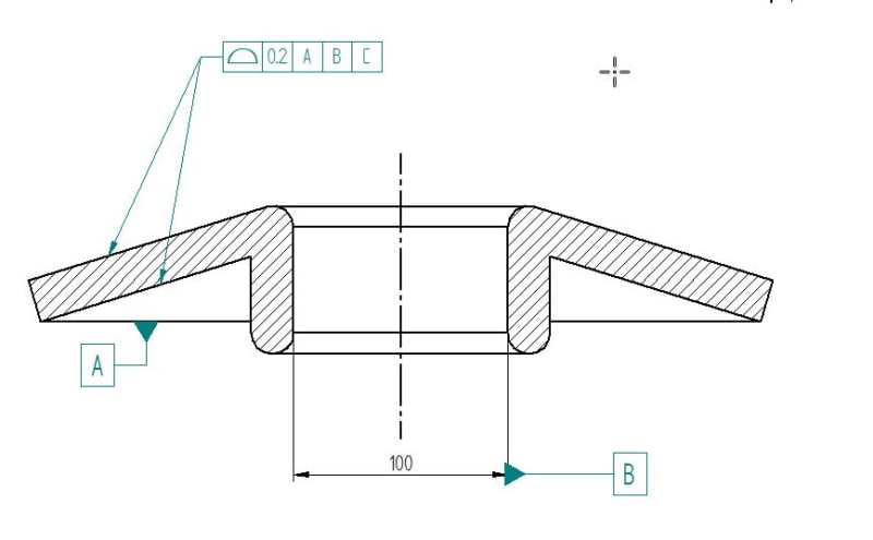
I was in trouble to understand if I can define in the drawing a primary datum starting from a datum feature edge.

Edge_Datum_Washer_cwq960.jpg


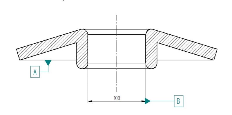
The particular shape of this washer do not allow me to select a plane as primary datum feature.

I did not find any example so far. Is that correct following ASME Standard ? Is valid at the same for ISO GPS.

Looking forward to read your opinions.

Thanks for helping me.

Filippo
 
Replies continue below

Recommended for you

Since that edge presumably continues around in a circular fashion, then it is already creating a plane. So everything's fine.
The edge itself is called the datum feature, but the theoretical plane it creates is called the datum.

John-Paul Belanger
Certified Sr. GD&T Professional
Geometric Learning Systems
 
Filippo, where would you like the part to be measured when it's done? On a CMM?
 
You can do that strictly from a drawing point of view but a sharp edge is easily damaged and depending on how it's produced, there may be some amount of break edge or radius making it a rather unreliable datum. Depending on function, you might want to create a basic gauge diameter to locate the part on one of the conical surfaces.

----------------------------------------

The Help for this program was created in Windows Help format, which depends on a feature that isn't included in this version of Windows.
 
filippoGDeT,

Seems questionable to be. Assuming you want the datum feature simulator to be a plane contacting the part, I'd consider avoiding the question by adding a narrow planar surface to the theoretical geometry of the part.


Belanger, dgallup,

Would you say that the meaning would be the same if the datum feature symbol had been attached to the same edge, but in a view where it's shown as a circle instead of a line?


pylfrm
 
pylfrm -- if I'm hearing you correctly, then no. That would be designating a diameter as the datum feature, and thus the datum would be an axis, not a plane.

John-Paul Belanger
Certified Sr. GD&T Professional
Geometric Learning Systems
 
Regarding pylfrm's question, I think if the datum feature symbol was shown in a view where the edge looks like a circle, I would still interpret that a planar datum feature simulator should be contacting that edge. Especially if the datum feature symbol was attached to a leader with an arrowhead pointing to the edge, which would probably be the least unclear way to specify it if it was shown in such a view.
The Y14.5 standard doesn't have such application covered though, maybe because an edge like that isn't considered a reliable datum feature from the reasons mentioned by dgallup. Perhaps if it is intended to be supported like that in the functional application a flat surface like pylfrm suggested is needed there anyway. That would also prevent the washer from scratching the surface of the other part.
 
Putting the question: "Is the circular edge is good functional datum feature in this application or not?" aside, I think the technique similar to the one shown on the picture below (taken from Y14.41) could be utilized. Two adjacent views could be used to show that the datum target simulator A1 is planar and that the derived datum A is a plane.

capture_uitern.jpg
 
Dear All,

First of all many thanks for the interest you shown in this topic. Of course this geometry is not a simple square block :) as many exercise you find in GD&T book.

Cr7 ; The idea is to inspect the part by CMM using cilindrical probe will be used to pick the points around the whole edge at defined angular position.

The result is a geometrical collection of points all at the same radius. Second datum will be an axis we can derive from the datum feature B . Finally the third datum will be a special key ( not shown in the image I posted ).

Considering this DRF dfinition the idea is to control the " dish effect " by use a Surface Requirment applied on both conical surface.

Is a valid definition from a metrological point of view ?

Thanks in advance for your further support.
Datum_feature_from_edge_surface_requirment_oqbrgf.jpg


Filippo
 
fillipoGDeT,

Could you describe in more detail how this part should assemble to its mating parts? *edit: and possibly a basic idea of how it functions?
 
filippoGDeT,

I suppose I should quit hedging. I will say that your scheme is not valid, based on the following justification:

ASME Y14.5-2009 para. 4.5 said:
A datum feature simulator, as defined in para. 1.3.17, shall be the inverse shape of the datum feature, unless otherwise specified.

I think it's pretty hard to argue that a plane is the inverse shape of a circle.


I agree with pmarc's suggestion.


pylfrm
 
The edge in this example is nominally a planar feature, but would it be more acceptable to identify it as a datum target and therefore not subject to the limitation?
 
filippoGDeT,

how did you end up doing it?
 
Status
Not open for further replies.

Part and Inventory Search

Sponsor