Continue to Site

Eng-Tips is the largest engineering community on the Internet

Intelligent Work Forums for Engineering Professionals

  • Congratulations KootK on being selected by the Eng-Tips community for having the most helpful posts in the forums last week. Way to Go!

edge reinforcement in rafts 2

Status
Not open for further replies.

wrxsti

Structural
Sep 18, 2020
196
hello again engtips fam

so i was looking on a boef for 3 columns in a section 2 external and internal

and i got a moment diagram like this
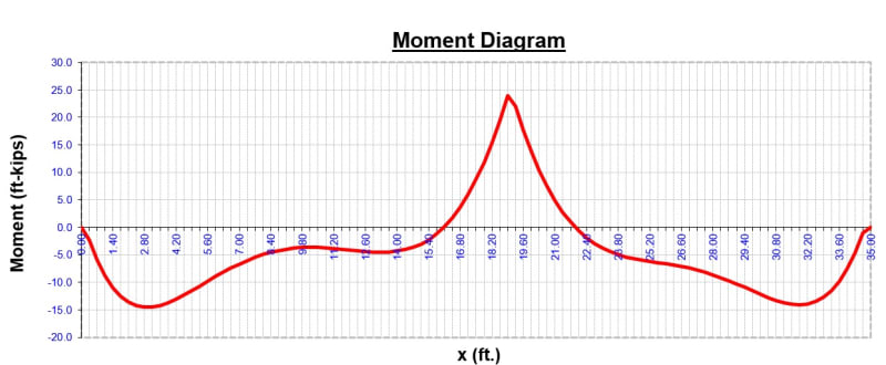
Untitled1_mq14lo.jpg

Z6qvt_beqghu.png


i notice however i see some details like this for the edge column/walls
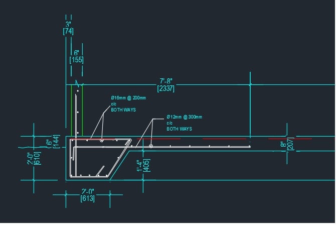
Untitled_sujqdy.jpg


where they have main reinforcement for the slab at the edge columns in the bottom?
and no beefing for the top reinforcement
the BM diag above (requiring top steel) seems be substantially higher to the edge which should have more reinforcement than the center to the
edge (approx 3x on that diag)

i know for continuous slabs you still need to reinforce the top for cracking on the outside edges even though not analyzed as fixed on the end.

but was wondering your opinions on this.

thanks in advance
 
Replies continue below

Recommended for you

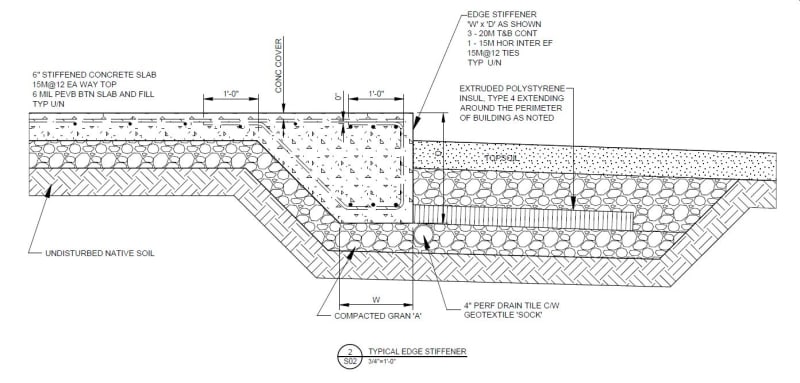
This is what I use...

Clipboard01_e53rtf.jpg


Rather than think climate change and the corona virus as science, think of it as the wrath of God. Feel any better?

-Dik
 
You may want to eliminate the bottom 12mm bars; they are likely in compresson. Similarly the hook at the end is not useful if you need to develop the bar you likely have enough for a compression development length. You want to have your edge reinforcing 'open'; it's easier to place rebar in the stiffener. Just some thoughts...

The 3 20M T&B in the edge stiffener are often 2 15M T&B and the slab is often 5" thick...

Rather than think climate change and the corona virus as science, think of it as the wrath of God. Feel any better?

-Dik
 
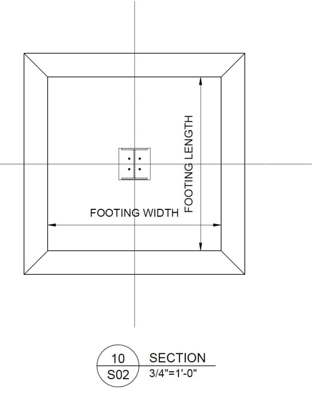
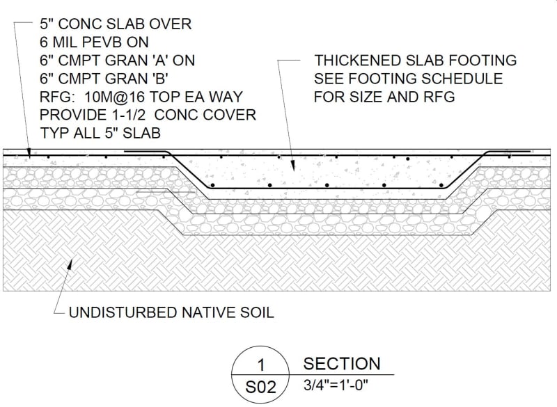
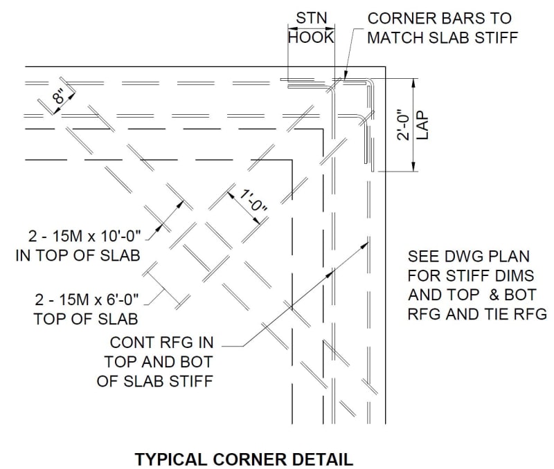
Some more details, I've used...

Detail1_mwaxfg.jpg


Detail2_zyqlmu.jpg


Corner_g7jrwj.jpg


Rather than think climate change and the corona virus as science, think of it as the wrath of God. Feel any better?

-Dik
 

The excerpt picture shows RC wall 6 in. thk. ( perimeter wall ?). Will you pls post the structural plan?

The BMD implies line loading at two ends and point loading at midspan..

IMO, provide double reinf. ( T& B )
 
thanks dik and hturkak

HTURKAK said:
The excerpt picture shows RC wall 6 in. thk. ( perimeter wall ?). Will you pls post the structural plan?

The BMD implies line loading at two ends and point loading at midspan..

i dont have a structural plan but it is as you described.
 
HTURKAK said:
IMO, provide double reinf. ( T& B )

well seeing there is some fixity should definitely have bottom reinforcement in the slab

lets look on (for discussion purposes simplified)

DIAGRAM POINT LOAD NEAR SUPPORT WITH END FIXED
Untitled2_cccvok.jpg

DIAGRAM POINT LOAD NEAR SUPPORT WITH END PINNED
Untitled3_vivmxz.jpg


fixed end moment is approx 90pc of simply supported moment

so top and bottom should be similar

what are your outlooks on this?

thanks again for taking your time to answer my questions again
 
Just a note: the raft you are designing has neither "fixed" nor "pinned" ends at the edge beams. Thus, basic beam table formulas do not apply. The correct boundary conditions - and therefore, the correct bending moment and shear force diagrams - are defined by an elastic foundation, the most simple of which is the Winkler discrete spring model.
 
centondollar yes

excuse my looseness i was trying to express that if the reinforcement was put in that location because fixity ( which we know doesnt exist in the analysis unless its connected to some rock mountain)

it should have been atleast equal to the top

 
Status
Not open for further replies.

Part and Inventory Search

Sponsor