Continue to Site

Eng-Tips is the largest engineering community on the Internet

Intelligent Work Forums for Engineering Professionals

  • Congratulations KootK on being selected by the Eng-Tips community for having the most helpful posts in the forums last week. Way to Go!

Effective embedment length for partially debonded anchor bolt

Status
Not open for further replies.

BridgeEngineer21

Structural
Oct 26, 2021
45
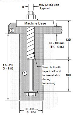
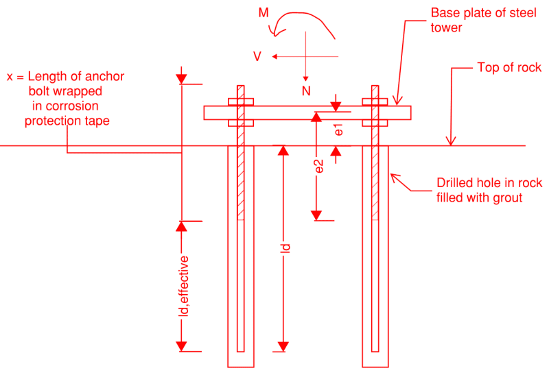
I am reviewing a proposed connection for a tower foundation that has the detail shown in the sketch below. The contractor wants to use corrosion protection tape at the top portion of the anchor bolt. They did not provide any info on the tape, and from the manufacturer's website I can see it is mainly geared towards wrapping pipes and things like that so they don't give any structural properties or friction coefficient for it.

Therefore, I believe the length of the anchor bolt covered in this tape should be assumed to be completely debonded from grout. This means that for anchor bond strength, only the length ld,effective should be counted on.

Now my question is, what about for other checks such as pullout, breakout, or pryout? Intuitively, it seems those are all based on the depth of concrete (or in this case, grout and rock) above the bottom of your anchor, and there's no need to discount the debonded portion of the anchor. But I've never dealt with a case like this before, and would like to get a little confidence with some second opinions.
Capture_f1dwkt.png


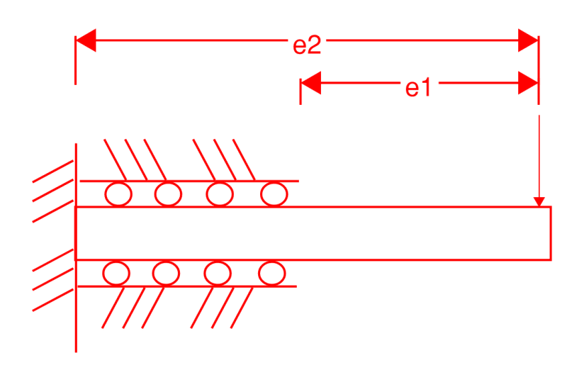
A related question is having to do with the check of bending in the exposed portion of anchor bolt. Intuitively, it seems the moment can just be V*e1, since below e1 the compressive strength of the grout should prevent the bolt from deflecting at all. But then I looked at the situation as basically equivalent to the one sketched below, which I again have never really analyzed before, and now I'm a bit in doubt if I'm not missing some other aspect.
Capture2_qaokiu.png


Would appreciate anyone's thoughts on this.
 
Replies continue below

Recommended for you

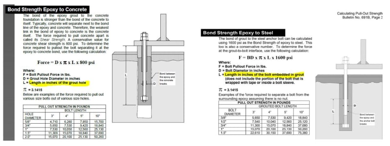
have a look at this literature from Chockfast see p. 7 of the document.

grout_aut0b5.jpg


Thanks for sharing dvd, interesting read. It confirms my thinking about bond strength. But in the section about pullout strength they don't directly address if the embedment length would be effected by having anchor tape.

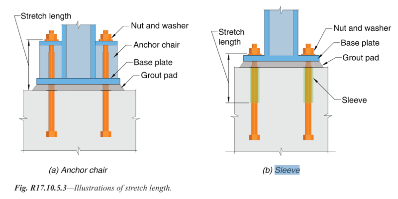
However the main value I got from this is to remind me about anchor sleeves. While I haven't designed with those before either, I'm much more familiar with seeing them in my typical line of work. I took a look into ACI 318 and Eurocode 2-4, and found that both of them only address sleeves with regards to "stretch length" for seismic design (example from ACI below), which I think should be similar to e2 in my case (though of course, in a case where I actually needed to count on the stretch length to allow some displacement, then I would go with only e1, since maybe there is more bond than I think with this tape). But I couldn't find anything about how this stretch length effects embedment length.

Capture_telywd.png
 
Don't the prior pages of that literature address this?

grout1_hz3cvj.jpg
 
Those pages are talking about bond strength, and they are helpful just to confirm my assumption about how I should account for bond strength. But bond strength is not what I had doubts about. My doubts are related to other cases such as pullout or breakout, as well as bending in the anchor bolt.
 
Idle interest from an EE here. The linked document speaks of the bond strength of epoxy grout to concrete, but the OP has the grout in rock of an unnamed type. Seems like this detail might make a difference.
 
Good point stevenal, that's correct. The contractor has specified the rock type, and are using adhesion and friction coefficient properties *that are supposedly* specific to the interface between the rock and the grout. (*Though, I'm a bit in the dark where the properties they're using are actually coming from, and will question that with them too, but that's another story).
 
There is some difference between an grouted/epoxied anchor with a stretch length (tape or sleeve) and a headed anchor. In the case of the headed anchor, where all of the anchorage force is delivered at the bottom, it makes sense that other failure modes like breakout and pryout would be unaffected. In a grouted or epoxied anchor, where the anchorage force develops across the effective length, perhaps there is some effect. If the stretch length were 25% of the total, I wouldn't lose sleep over it. If more, perhaps you account for it (although I'm not sure how).
 
Bond or pullout could be affected, but a breakout cone wouldn't be. Your breakout cone isn't smaller because of the reduced bond along the top part of the cone. The bottom part of the cone would still need to come out through the area that the top of the cone exists in (i.e. you can't just breakout a shear cone in the bottom part of the anchor without the top part coming along for the ride, even if the part around the anchor is debonded)
 
Thanks TLHS, that confirms what I was thinking there.

I am now thinking that pullout isn't a case I should consider, since there is no head or nut at the bottom of the anchor bolt, the "pullout" capacity would just be the same as the bond strength between anchor bolt and grout.
 
Agreed, no "pullout", only bond.

THLS, I'm not sure. Would the changes to the stress field when partially debonded change the assumed geometry of a breakout cone? It feels to me that it might -- most likely making it more similar to a headed anchor, but I'm not confident enough in my understanding of this scenario to say that for sure.
 
Does anyone have thoughts on the second part of the question? Is bending affected at all or is e1 for the moment arm still valid?
 
I am now thinking that pullout isn't a case I should consider, since there is no head or nut at the bottom of the anchor bolt, the "pullout" capacity would just be the same as the bond strength between anchor bolt and grout.

Assuming the anchor rods are smooth, yes all you'd have is the bond strength, which would require some very deep anchors to develop the capacity. If the anchor rods are threaded rod (which would be typical for this situation) you'd get some mechanical interlock with the grout, which would shorten the necessary length. Epoxy adhesive anchorage would provide the capacity with shallower and smaller diameter holes than grout.

For grouted holes, is the diameter too small for a nut or a threaded coupler on the bottom?

 
How would you account for the mechanical interlock between the grout and rebar to increase the bond capacity? I believe that is included implicitly in typical rebar development length equations, and the pullout equation for anchor bolts in the codes I have seen only accounts for bearing area under the anchor head.

The holes could fit a nut. My main hesitation is there is no nut shown on the conceptual drawings my company developed (before my time here) either, so I'm hesitant to just call for new items and invite scrutiny. Of course, if I find that it was an oversight on our drawings and is truly required for capacity, then I will take this opportunity to correct it.
 
I didn't realize these were rebar anchors. For that, yes, the rebar development would be applicable, assuming they're deformed bars. I thought they were proposing smooth anchor rods, where you would only be able to use the chemical surface bond strength, with no mechanical interlock. That doesn't give you much force transfer.

 
Sorry, that was a typo. These are anchor bolts, M-series to Eurocode. So there are threads, but I guess probably not large enough to develop meaningful interlocking forces like with a rebar.
 
Does anyone have thoughts on the second part of the question? Is bending affected at all or is e1 for the moment arm still valid?

The fixity question is a tricky one, especially with the wrap. I think there are equations for the depth to lateral fixity for bars/bolts embedded in concrete, but I'm not sure where to find them. However, that depth would increase some because of the wrap, and it would vary depending on how thick/tight the wrap is at the surface of the concrete. We avoid that whole dilemma by keeping our leveling nuts less than a bolt diameter from the top of the concrete, which allows us to ignore the effects of bending, per the AASHTO sign spec.
 
I guess probably not large enough to develop meaningful interlocking forces like with a rebar.

I think it may depend on the type of grout. It's been quite a while since we used it, but we used to anchor threaded rods using epoxy resin grout. The depths were not excessive (12" for 1.25", 36 ksi threaded rod). We've moved to epoxy adhesive anchorage systems now (Red Head C6+, Hilti HIT-RE 500 V3, etc.) which have published required embedment depths anchoring threaded rods. They require much smaller holes than the grout, but they require very good QC for installation. Thorough cleaning of the holes and thorough mixing of the epoxy are critical in tension applications.
 
Interesting that that paper explicitly defines pullout failure as equivalent to bond failure:

Paper on Anchorage Systems for Limestone Structures said:
Bond or pull-out failure occurs when the shear stress on the embedded surface of the anchor exceeds the adhesive bond strength prior to any other mode of failure occuring.

ACI 318 on the other hand defines pullout failure and bond failure as two separate cases, with pullout based on just bearing underneath the head of the anchor. I did just notice this sentence:

ACI 318 17.6.3.2.1 said:
For post-installed expansion, screw, and
undercut anchors, the values of Np shall be based on the 5
percent fractile of results of tests performed and evaluated
according to ACI 355.2. It is not permissible to calculate the
pullout strength in tension for such anchors.

If I'm understanding that right, the type of anchor I have here is a post-installed screw anchor, so they're saying a pullout strength is not possible to calculate and can only come from testing.

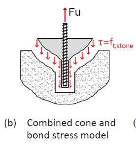
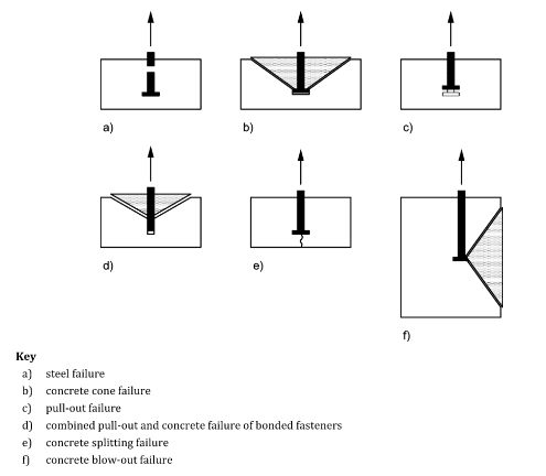
Eurocode (EN 1992-4) is a little less explicit, but is the governing code I have to follow here. I am thinking that the combined pullout and concrete cone failure mode, as you posted above, is the main failure to check here. I'm wondering if there's any significance to the fact that in the Eurocode figure that's the only failure mode they showed a non-headed anchor with..

Capture_qjnmnl.png


I guess the failure angle of the "rock" cone would then depend on the joint inclination angle of the rock
 
Status
Not open for further replies.

Part and Inventory Search

Sponsor