Continue to Site

Eng-Tips is the largest engineering community on the Internet

Intelligent Work Forums for Engineering Professionals

  • Congratulations KootK on being selected by the Eng-Tips community for having the most helpful posts in the forums last week. Way to Go!

Effective Length of a Bottom Chord when a Mixture of Tension and Compression Present 1

Status
Not open for further replies.

ENGUCR

Structural
Sep 23, 2017
37
Hi,
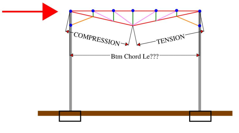
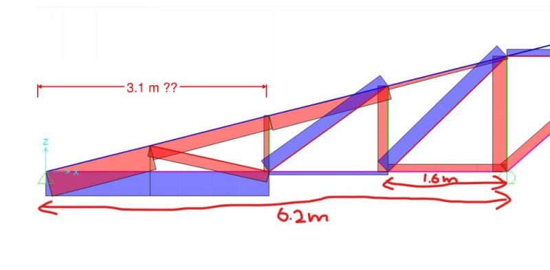
I need a bit of advice on the selection of effective length for the compression capacity calculation of bottom chord of a truss(double inverted) when there is a mixture of tension and compression in this chord member. Please see the attached axial force diagram. What length should I use for this out of plane buckling? is it the entire length of chord member or the segment length of the compression part?
Tx in advance
 
 https://files.engineering.com/getfile.aspx?folder=d4007882-1808-4643-85d8-54e57271b1ef&file=Annotation_2021-01-06_181803.jpg
Replies continue below

Recommended for you

ENGUCR said:
is it the entire length of chord member or the segment length of the compression part?

1) It's the entire length between points of lateral restraint, regardless of how the axial load diagram shakes out.

2) The concept to keep in mind and to guide your decision making is that the effective length needs to represent the length of member that will physically displace laterally when buckling occurs. Obviously, you'll get displacement all along the length of the chord from one point of lateral restraint to the next including the point on your chord where the compression switches to tension. That's the key.

3) Relative to an all compression situation, you are correct in thinking that the capacity of the chord will increase for the fact that the chord experiences tension over part of it's length. Unfortunately, it gets considerably more complex to design a compression member taking account of that without resorting to an FEM buckling analysis. On the other hand, if you're comfortable doing the FEM buckling analysis, have at it. Personally, I'd only go that route if I were desperate for capacity such as in a renovation application etc.
 
Along similar lines of discussion...

How about this hypothetical situation: The blue dots are the hot-rolled purlin locations and are points of lateral restraint and are rigidly connected to the hollow section truss verticals, so as to provide lateral restraint to the bottom chord. Sort of a trussed moment frame setup, which under the lateral loads puts the first half of the bottom chord into compression.

Aside from a full blown FEA buckling analysis, are there any simple tests you could perform to validate the stiffness of the bottom chord lateral restraint. Something along the lines of applying a unit load at the mid point of the bottom chord and back-calculating an equivalent spring stiffness - then comparing that to some previous buckling guidance in some textbook/code.

Le_mdu3ze.jpg
 
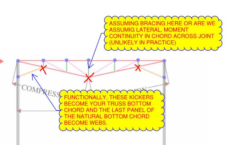
Gotta get some preliminaries out of the way first:

1) Are we to assume no bracing at the locations shown below? In practice, I'd usually deem these "must brace" locations.

2) Are we assuming out of plane flexural continuity across the bottom chord pitch break at mid-span?

C01_xpdph6.jpg
 
This is an interesting question. If it is a steel truss, I think you would be much better off using the direct analysis method outlined in AISC and circumvent finding the "correct" k-factor. Conceptually speaking, it is still valuable to think of buckling in terms of effective length (finding the half-sine of the buckled shape), but direct analysis method is just easier to use in practice.

Buckling is entirely a matter of stiffness. It's easy to find k-factors from that table in the appendix of AISC which classifies effective length based on end conditions (pin-pin, pin-fixed, etc.), but how many times do you actually have infinitely rigid connection or completely pinned supports? Another alternative is to use those alignment charts, but I'd be curious to see how many engineers still use those.

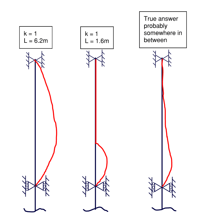
I assume your unbraced length out-of-plane is 6.2 m? Assuming the entire bottom chord is in compression, and that two supports remain in the same plane, and that they do not provide any rotational stiffness, the worst-case k is equal to 1. But since the destabilizing influence of compression only affects 1/4 of the bottom chord, it's probably less than 1. Here is a sketch to show what I mean (top view of the truss).

Screenshot_2021-01-15_103557_bwyuqt.png
 
Trenno, looks similar to a U-frame (aka pony truss) situation. Bridge codes often have a procedure to convert the lateral stiffness to effective length. I think I've seen it in the US aluminium code as well.

When you say full blown FEA, do you mean something more complex than an elastic buckling analysis? I think that's an appropriate method and not too onerous to apply in this case.

Not so sure about direct analysis. K=1.0 is a given but over what length? If you use the full truss chord length and maximum compression, I think you would underestimate the capacity.

(Waiting for Newmark to put in an appearance)
 
The short simple answer is this:

Kootk said:
1) It's the entire length between points of lateral restraint, regardless of how the axial load diagram shakes out.

The more complex answer that gets you a more efficient design is:

wcfrobert said:
I think you would be much better off using the direct analysis method outlined in AISC and circumvent finding the "correct" k-factor.

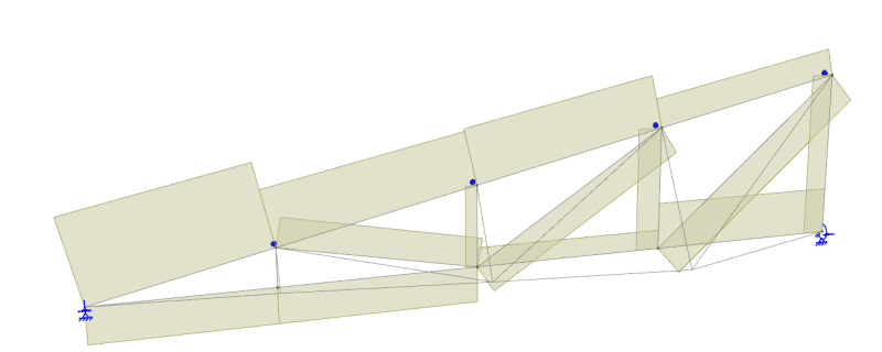
For demonstration I mocked up a model approximately similar to yours and I get an effective length of 2.3m. (I was initially getting ~1.6m which surprised me, this was caused by rigid connections of the web members. I made these pinned and the effective length increased to 2.3m.)

temp_cgcix0.png

The first buckled shape is shown.
 
human909 said:
For demonstration I mocked up a model approximately similar to yours and I get an effective length of 2.3m.

Does that not seem a little fishy as a benchmark for OP's case given that the length shown below, with a constant axial force, is 3.10 m? Surely the effective length must be bounded by 3.10m and 6.20 m?

C01_jzu9lw.jpg
 
I did some related work on this in a past thread which maybe of interest here. Everything that follows is a regurgitation of that work.

-----------------------------------------------------------------------------------------------------------------------------------------

I prepared the attached PDF to answer some questions that I've been interested in since Celt83 conducted a similar exercise. And I thought that they might be of interest to the group. Basically, I wanted to study the flanges of our W27x84 test beam as isolated compression members to get a sense for how the behavior and capacity of such members would be affected by a compression distribution that varies over the length of the member and is substantially tension over segments of the member.

My observations:

1) In many important respects, a beam cannot be considered to be merely an assembly of independent axially loaded fanged. No surprise there. This representation completely ignores that fact that both flanges are continuously braced, to a degree, by the St.Venant torsional stiffness of the beam. That makes a big difference and must be remembered.

2) Relative to a classic, Euler column, a column loaded like a beam bottom flange would have about double the capacity.

3) A column loaded like a beam bottom flange still buckles over its entire length, as our LTB models have suggested.

4) Relative to a classic, Euler column, a column loaded like a beam top flange would have about fifteen times the capacity. Clearly, a flange with its compression field located at its ends (bottom flange) is much more unstable than a flange with it's compression field located at its middle (top flange).

5) I've come to view LTB, at least for our test case, as something like:

a) the bottom flange initiates some twist.

b) with some twist in play, some of the applied load becomes a weak axis load on the beam and initiates some sway.

Obviously, these are two actions occurring in tandem rather than sequentially.

C01_rsiogp.jpg


kootk said:
Does that not seem a little fishy as a benchmark for OP's case given that the length shown below, with a constant axial force, is 3.10 m? Surely the effective length must be bounded by 3.10m and 6.20 m?
No. Though that is a reasonable question, which deserves an explanation. (NOTE: I have assumed that BLUE=TENSION, RED=COMPRESSION as this makes sense with assumed loading.)

The 'effective length' calculated through buckling analysis is back calculated from the critical buckling load. Due to significant sections of that chord being in tension the effective length is significantly lower.

The approach used is described here:

As it describes the estimated buckling lengths for the members not involve in buckling are overestimated and so are conservative. In this case the member that we are concerned with buckles first so the effective length is a rational approximation from the buckling analysis.

Another way to look at it is to focus on the compression member on the far right which is 1.6m long and consider it as a sway member. Since one end is fixed and one isn't we can put the upper bound at the Euler theretical value of 2x or 3.2m.
 
human909 said:
NOTE: I have assumed that BLUE=TENSION, RED=COMPRESSION as this makes sense with assumed loading

That explains the difference as I was assuming the reverse. I do suspect that your assumption is the correct one however. Thanks for helping me get it sorted.
 
KootK said:
Thanks for helping me get it sorted.
No problems.

As you may have picked up from previous posts I rely heavily on computational packages to do the heavy lifting for me. I pretty much never calculate my own effective lengths, I let buckling analysis do it for me. It seems like a black box until dig deeper into it and then it all makes sense. Knowing how you black box works is obviously pretty important.

Out of curiosity do you or many others here use similar for such analysis? Or is it manual calculation of effective lengths?

EDIT:
KootK said:
5) I've come to view LTB, at least for our test case, as something like:
Interesting.... I wasn't immediately solving the problem from a LTB perspective but a discrete compression element perspective. Both should come to similar conclusions. Though this does in a roundabout way show that the LTB concerns expressed about AS4100 as confirmed by this example where the effective length is greater than the compression cord length.
 
steveh49 said:
Not so sure about direct analysis. K=1.0 is a given but over what length? If you use the full truss chord length and maximum compression, I think you would underestimate the capacity.

What I'm saying is that the effective length (kL) is bounded between 1.3 m and 6.2 m. It would be most conservative to assume 6.2 m (maybe too conservative)

Thanks for sharing KootK. That's an interesting study. Inspired me to do a MASTAN model of OP's problem.

I did an elastic critical load analysis and got an unbraced length of 2.38 m (similar to what human909 got). I'll post some screenshots of my model later tonight.
 
wcfrobert said:
I did an elastic critical load analysis and got an unbraced length of 2.38 m (similar to what human909 got).
Nice! [2thumbsup]

wcfrobert said:
What I'm saying is that the effective length (kL) is bounded between 1.3 m and 6.2 m.
Would you agree that we could get a tighter boundary treating the 1/4 chord as a Euler sway member. Which would give a maximum effective length of 2x the length 2x1.6=3.2m?
I can answer my own question here. No, as the end conditions are not analogous to a Euler sway member (no completely rigid end restraint). In some cases you do get an effective length greater than 2x the compression section length.
 
Human, I would use elastic buckling analysis for this too. You and wcfrobert both did it in spare time which shows how quick it is. A 'quick' hand check probably takes as long or longer but may not be the end of the story whereas the buckling analysis probably is the final solution. As a general rule, something that's simple enough to do by hand will be simple enough to do quickly using software.

It depends of course on whether all the restraining elements are modelled. In Space Gass (for example) you may be better off using the member design function just to automate the code check by inputting the restraint locations rather than modelling the restraint itself for the bucking analysis. Similar if the buckling analysis is too conservative for some members: use the code 'hand' method for those whilst using the bucking analysis for the non-obvious members.
 
steveh49 said:
It depends of course on whether all the restraining elements are modelled. In Space Gass (for example) you may be better off using the member design function just to automate the code check by inputting the restraint locations rather than modelling the restraint itself for the bucking analysis.
Maybe I'm being pedantic or maybe I'm just confused but I thought I'd dispute this a little to clear things up.

In SpaceGass the only restraint locations you can input are the LTB flange restraint conditions. These affect codes checks for LTB but not for axial compression which is the critical case for the lower chord here. For the axial compression check you can use the buckling results or a hand calculated effective lengths.
 
Typically if you have an analysis model to work out your normal design actions, then you're a few clicks away from the answer to a compression buckling analysis. People who think it involves some extra amount of modelling or design are mistaken as long as the software you're using is able to do a buckling analysis of course. I find the biggest barrier is that it's not something people are too familiar with, and it all sounds outside their comfort zone.

In NZS3404 and AS4100 standards, it's almost quicker to get to an answer for compression buckling vs guessing the effective length and going through the normal design provisions. Guessing, that's what you're doing otherwise and honestly you have no idea if you're right, wrong, conservative or non-conservative. If I have a situation where the section changes between restraints or the load changes between restraints, or the restraints are not uniformly spaced, you should probably be using a buckling analysis for the most efficient design and analysis.

But I also agree that the direct analysis method is also useful here, but you do have to have some idea of the buckled shape to apply the notional loads in an appropriate way.

If of interest as part of that thread kootk linked to on rafter restraint I did a 6 part blog series on my personal blog going through the basics of undertaking buckling analyses. Though to NZS3404 and AS4100, the concepts equally apply to AISC, or other codes. You can find the 6 parts linked here.
 
Human, I think you are correct. I was thinking of Microstran, but you still have to give the k factor. What I was really trying to say is that mixing buckling analysis results for some members with 'hand' k factors for others is sometimes the way to go.
 
I agree. An eigenvalue buckling analysis is pretty quick to do and is likely better than hand calc. It is still valuable to double check with some hand calc to verify the software results.

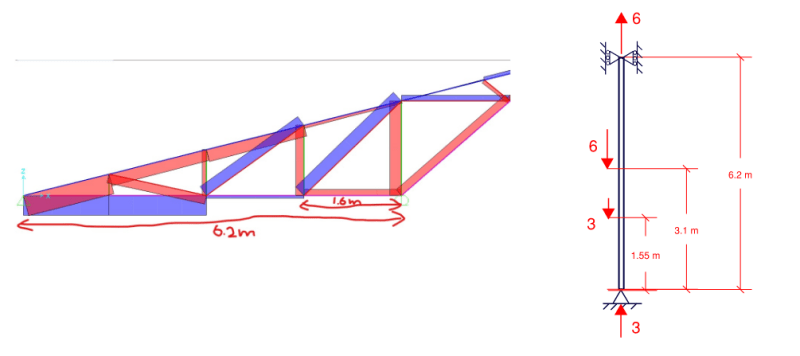
I ran a quick elastic critical load analysis on MASTAN for OP's problem. I simplified the bottom chord into a pin-pin column by assuming the web members do not contribute any out-of-plane stiffness. I also added some axial load to emulate the axial load diagram shown in OP's truss where the bottom quarter is in compression, while the top third is in tension.
Screenshot_2021-01-15_163010_tuta37.png


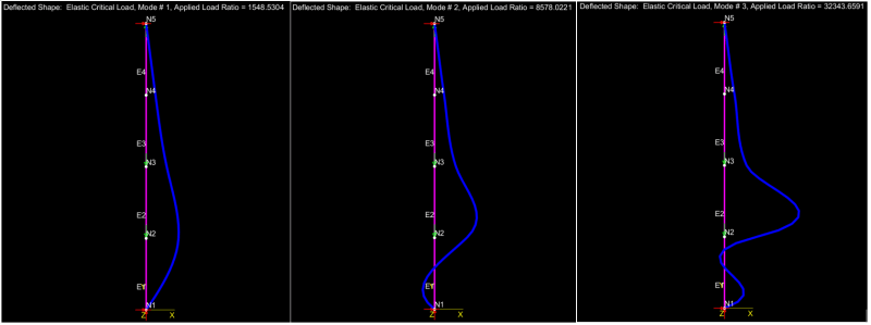
I assumed a 20 mm by 20 mm square section (A = 400, I = 13333). Here are the first three modes of buckling with load factor 1548, 8578, 32343.
Screenshot_2021-01-15_203003_qn3la7.png


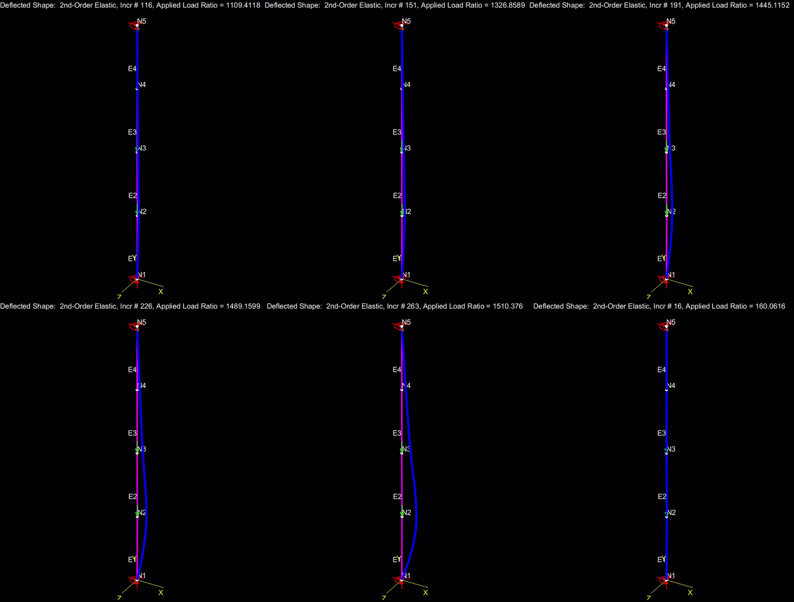
I also ran a second-order elastic analysis. The load ratio at which bifurcation occurred is around 1515 which confirms the result above.
buckling_gif_a3r99a.gif


Therefore, the critical load for my assumed member is 1548*3 = 4644 N. From this we can back-calculate the effective length from the euler buckling formula: kL = sqrt(pi^2 * E * I / Pcr) = 2380 mm.
 
human909 said:
Out of curiosity do you or many others here use similar for such analysis? Or is it manual calculation of effective lengths?

I doubt that I use FEM buckling analysis more than once or twice a year in my production work. It breaks down like this for me:

Non-Sway Frames: K-factor as it produces similar resutls.

Sway Frames: AISC Direct Analysis Method as it produces similar results.

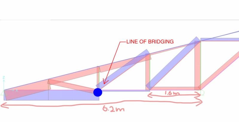
Trusses: K-Factor. This will usually produce similar results for me because I'm a habitual over-bracer. I would normally have taken one look at that bottom chord axial force diagram and specified a line of bridging as shown below. I realize that the bridging isn't free, monetarily or environmentally, but that would be the way of it for me unless:

a) I was really trying to please an architect with a clean overhead look;

b) I was trying in desperation to make some existing thing work without remediation;

c) I was making a specialty of steel truss design and wanted to be known as "the no bridging guy" for marketing purposes.

I've got no beef with other's using advanced analyses in their on production work but, for me:

d) I find advanced analyses difficult to check unless I actually review the model myself or the designer did an uncommonly good job of recording their assumptions.

e) I just don't "feel" buckling analyses like I do K-factor and the Direct Analysis Method. I'm familiar with the derivations and all that jazz but, somehow, it's still too mathy to appeal to my intuition. KootK limitation I guess.

I feel like a modern, big time bridge design engineer would have much cause for using FEM buckling analyses but, sadly, I only do very small / conventional bridge stuff.

C01_wtdsoz.jpg
 
Status
Not open for further replies.

Part and Inventory Search

Sponsor