Continue to Site

Eng-Tips is the largest engineering community on the Internet

Intelligent Work Forums for Engineering Professionals

  • Congratulations KootK on being selected by the Eng-Tips community for having the most helpful posts in the forums last week. Way to Go!

Effective Length of a Bottom Chord when a Mixture of Tension and Compression Present 1

Status
Not open for further replies.

ENGUCR

Structural
Sep 23, 2017
37
Hi,
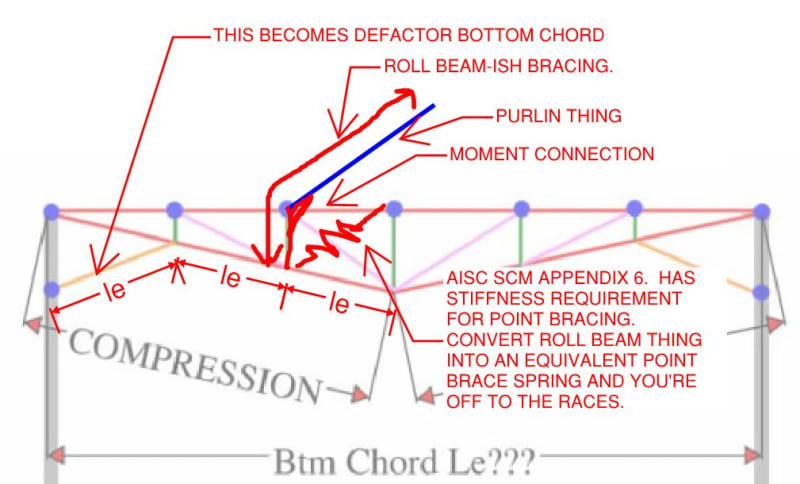
I need a bit of advice on the selection of effective length for the compression capacity calculation of bottom chord of a truss(double inverted) when there is a mixture of tension and compression in this chord member. Please see the attached axial force diagram. What length should I use for this out of plane buckling? is it the entire length of chord member or the segment length of the compression part?
Tx in advance
 
 https://files.engineering.com/getfile.aspx?folder=d4007882-1808-4643-85d8-54e57271b1ef&file=Annotation_2021-01-06_181803.jpg
Replies continue below

Recommended for you

Thanks for that explanation Kootk, quite enlightening. For what it is worth:

I don't use FEA for buckling analysis for my day to day work. I've used more in discussions involving you than anywhere else! I think I've used it once or twice for genuine work. I do use FEA regularly in my work but I work in a structural/mechanical field so it makes sense for complex storage vessel designs.

The buckling analysis (eigenvalue) tool in my structural modelling program (SpaceGass) is essential for my workflow. I essentially never calculate effective lengths myself. Like you, but for different reasons, this approach does sometimes mean that my bracing is a touch conservative.

Regarding checkability of the buckling analysis in most cases I find it relatively trivial. And unless you have erroneous restraints in your model it is extremely reliable and conservative. Regarding LTB however you are left on your own to interpret and input appropriate restraints. I spend far more time considering LTB inputs.
 
KootK said:
Gotta get some preliminaries out of the way first:

1) For arguments sake, let's say we can't brace these locations for aesthetics.
2) Let's assume the kink point is butt welded and thus has full minor axis moment continuity.

steve49 said:
When you say full blown FEA, do you mean something more complex than an elastic buckling analysis?

I was being a little exaggerated here, I did mean an elastic eigen buckling analysis. I think the reason I phrased it like this is because, as Agent eluded to, using this method to determine effective lengths may not be as familiar for most design engineers.

steve49 said:
Bridge codes often have a procedure to convert the lateral stiffness to effective length.

I've gone through this process once with the Eurocode bridge code. The equations get pretty long and convoluted. I remember reading the old AS4100 quoted a stiffness value rather than the 2.5% axial force lateral restraint requirement.


Additional question regarding original structure in my post above: what would be the process to narrow down which is the governing ULS lateral combination to use within an elastic eigen bcukling analysis? Just thinking in a 3D frame, some combinations may produce greater utilisations in the restraining members yet lower forces in the members of interest (eg top/btm chords). Or would you go down the computationally expense route of running each ULS combo as a separate buckling analysis?
 
Trenno said:
Aside from a full blown FEA buckling analysis, are there any simple tests you could perform to validate the stiffness of the bottom chord lateral restraint.

I'd handle it like this in the parlance of US steel design practice. This is similar to your unit load suggestion but the unit load would be applied to the roll beam thing in isolation to determine an equivalent point brace to represent it.

C01_sckll5.jpg
 
Thanks KootK - I don't have access to that reference unfortunately, but does it spit out a stiffness in terms of kN/mm?

Do you have any thoughts on determining which ULS load combo to take forth into a buckling analysis?

 
Trenno said:
I don't have access to that reference unfortunately...

You can find it free & legal here: Link

Trenno said:
...but does it spit out a stiffness in terms of kN/mm?

Yup, or at least the imperial unit equivalent.

Trenno said:
Do you have any thoughts on determining which ULS load combo to take forth into a buckling analysis?

You're barking up the wrong tree on that one. We'll have to let the gents who are using the technique for routine production tell us how it's done. I have been thinking about this though and, from a reviewer standpoint, it seems to me that I'd want DCR for the governing ULS load case for every compression member in a complex frame. In my mind, that sounds like:

1) Cycle through all of the ULS load cases and;

2) For each ULS load case, generate enough buckling modes such that you hit the governing buckling mode for each compression member.

That sounds computationally intense but maybe that's no longer an limiting factor.

 
Trenno said:
Do you have any thoughts on determining which ULS load combo to take forth into a buckling analysis?
Pick the the most severe or do all of them if the most severe isn't obvious.

Kootk said:
1) Cycle through all of the ULS load cases and;

2) For each ULS load case, generate enough buckling modes such that you hit the governing buckling mode for each compression member.

That sounds computationally intense but maybe that's no longer an limiting factor.
Yep all ULS loads are cycled through.

The difficulty in obtaining every bucking mode for every compression member is that your frame often starts to collapse after one or a couple of members start to buckle so the rest of the results would be invalid.

The approach of SpaceGass is to back calculate the effective length for each member at the critical buckling mode. The critical buckling mode may only be a couple of elements of the frame. It does result in conservative effective lengths for some members but by definition they generally aren't critical members anyway. It beats having to determine hundreds of effective lengths and you can always look through and manually edit effective lengths if you desire.

[URL unfurl="true"]https://www.spacegass.com/manual/Analysis/Buckling_Analysis/Buckling_effective_lengths.htm[/url]
 
human909 said:
by definition they generally aren't critical members anyway

Points 3 and 4 at the end of the Space Gass explanatory page linked by human can be important to this. Otherwise Space Gass would make all compression members equally critical in axial compression (equally close to elastic buckling), including those with notional compression only such as members that are primarily flexural.
 
steveh49 said:
Otherwise Space Gass would make all compression members equally critical in axial compression (equally close to elastic buckling), including those with notional compression only such as members that are primarily flexural.
Not quite. For a given load case the buckling analysis stops when the first member buckles. So it follows that the other compression members are further away from elastic buckling for that load case. Most members end up being not at all close to critical buckling.

The computed effective lengths for members under minimal compression might end up being 10x their actual length through this will rarely affect analysis. A quick review of one of my models reveals insanely high compressive effective lengths for the flexural members, though for code checks these are restricted to 5x.
 
That's what I'm getting at. If other software doesn't have the facility to limit to 5x actual length, all compression members would have significant utilisation under the axial load alone, so fail combined action check if only sized for flexure. I don't know whether all software has the ability that Space Gass has and, if not, the method has less attraction.
 
SpaceGASS's approach is an interesting and clever one. At first blush, though, it tilts me more in favor of the direct analysis method (DAM) given:

1) It sounds as though DAM would yield more accurate member capacities, and therefore more accurate DCR's, for non-critical members and;

2) My gut feel is that the future of software based stability design lies in ditching K-factors entirely rather adjusting them.

It's like The Matrix: the key to K-factors is to recognize that there are no K-factors. That's not quite true but you get the idea: the key to software based stability design is to recognize that we can do it without K-factors and, in many instances, do it better that way.

Presently, I still feel that all engineers should be trained in K-factor stability design prior to adopting other methods for production work. That, so that they can:

a) properly conceptualize basic stability problems in their heads before modeling.

b) check the software results.

C01_nqoaqd.jpg
 
KootK said:
I still feel that all engineers should be trained in K-factor stability design...

I completely agree with the sentiment of learning effective length method first! Nowadays, ELM is in the appendix of AISC as an alternative means of stability analysis which kind of indicate the direction we are going. Nevertheless, ELM is quite elegant and very logical and is pedagogically better than DAM. However, once you move from classroom to actual practice, things get messy and the idealizations we made no longer applies. So we end up relying on alignment charts and engineering assumptions.

DAM requires a lot of subtle understanding of material behavior and non-linear analysis. Otherwise it's is just remembering bunch of rules (notional load, stiffness reduction, second-order analysis, etc.). I think the most important insight here is that geometrically non-linear analyses inherently captures instability effects. Therefore, with a couple of adjustments to take into account residual stresses, initial out-of-plumbness, etc. you can get to a much better estimation than ELM.

We have so much compute power nowadays. It's weird to still rely on first-order results, amplify it by B factor, calculate k-factor with alignment chart, and so on when we can tick a single checkbox in the software to do a second-order analysis.


Trenno said:
Do you have any thoughts on determining which ULS load combo to take forth into a buckling analysis?

Elastic critical load analyses only rely on the relative distribution of your loads, not their magnitude. The critical applied load ratio would adjusts accordingly to give you the correct critical load. (e.g. if the critical load is 1000 kips, and your applied load is 1 kips, the ALR is 1000. If your applied load is 500 kips, then the ALR is 2).

As such, I think you should use the most likely load-distribution. But you should check all the cases (gravity, wind, seismic) and get a critical load for each. I think critical load analysis focus on behavior rather than design. It should only ever be used as a screening tool to identify potential stability failure modes. It's not straight-forward to convert critical load to design strength.

 
All this technical talk is making me feel incredibly lazy... i’d have stuck in a bottom chord brace and taken the effective length as 0.85 x unrestrained length.. Job done.

I need to brush up on my buckling analysis it seems!
 
It's not straight-forward to convert critical load to design strength.

I'm not sure I totally agree with that. AISC for example, allows you to use the critical buckling stress (determined by back-calculating for your section from the critical load) determined from a rational buckling analysis directly in the normal code buckling equations. Seems very simple to me.

Australian and NZ steel standards have a very simple formula to convert the critical buckling load to an effective slenderness which is then used to calculate the normal member capacity that perfectly matches the effective length method. It's almost less effort in a certain sense if you already have an analysis model of the elements you're interested in (you can see the two method outlined here with a contrived albeit simple scenario).

Totally agree on the load distribution, that is all that matters to model buckling under a certain loading scenario. Magnitude of loads applied are somewhat arbitrary as it just alters the buckling load factor but you arrive at the same critical load as some multiple of the applied load times a buckling load factor. So in the sense of the original question, you should be investigating all load cases/distributions. Just like you normally would, however under certain cases the member(s) you're looking at might not be the most critical. That just means something else failed first before the member of interest. EDIT - it's an important distinction to point out here that the critical buckling load that spits out of the analysis is not equivalent to the member axial capacity that you might calculate in the normal effective length method (just mentioning it because it is a misconception that some people interpret it as this)
 
Another of my concerns with advanced stability analyses is that stability tends to become "un-deliberate" from the perspective of the designer. This is what I mean by that:

1) With classical methods, one would rationalize which elements of a frame were stabilizing it and how. You'd then design those elements accordingly and, if other sources of stability were present but unaccounted for, so much the better.

2) With advanced, software based stability methods, it becomes a very easy thing to build yourself a model, apply your assumptions as you see fit, and then just let the software tell you if there is or isn't a stability problem. Where unintended or unconventional sources of stability exist, they will be accounted for whether the designer is cognizant of it or not.

These processes feel quite different to me from a reliability standpoint. Much comes down to the skill of the user of course. In my opinion, the voices chiming in on this thread probably represent the upper 1/3 rd of the "talent" out there when it comes to stability design. Also in my opinion, and greatly influenced by my experiences at Eng-Tips, there also exists a lower 1/3 rd who are likely to screw this up badly and regularly.
 
Agent666 said:
I'm not sure I totally agree with that. AISC for example, allows you to use the critical buckling stress ...

Wow nice blog. Lots of interesting content. Seems like you had similar discussions before. You are right. I had forgotten you can calculate Fe from analysis. I think DAM allows each member to be designed with k = 1 so I had never done the stuff you've outlined in the blog post.

KootK said:
Another of my concerns with advanced stability analyses is that stability tends to become "un-deliberate" from the perspective of the designer ...

Agreed, I remember hearing somewhere that it's better to be in a under-designed steel building than an under-braced steel building. I can't remember where I heard this though.
 
KootK said:
Another of my concerns with advanced stability analyses is that stability tends to become "un-deliberate" from the perspective of the designer. This is what I mean by that:

1) With classical methods, one would rationalize which elements of a frame were stabilizing it and how. You'd then design those elements accordingly and, if other sources of stability were present but unaccounted for, so much the better.

2) With advanced, software based stability methods, it becomes a very easy thing to build yourself a model, apply your assumptions as you see fit, and then just let the software tell you if there is or isn't a stability problem. Where unintended or unconventional sources of stability exist, they will be accounted for whether the designer is cognizant of it or not.

In my (limited) experience, I have not observed much of this type of issue with steel framed structural design. If you use appropriate member connection fixities and don't rely on floor diaphragms for load paths you can keep the process load paths clear and coherent in the model.

KootK said:
In my opinion, the voices chiming in on this thread probably represent the upper 1/3 rd of the "talent" out there when it comes to stability design. Also in my opinion, and greatly influenced by my experiences at Eng-Tips, there also exists a lower 1/3 rd who are likely to screw this up badly and regularly.
What is the alternative for the lower third?

One screw up I have seen is exactly the one pointed out in the SpaceGass help file. An external consulting engineer with far more years than I sent me his model of a structure. An 'A' frame on one side of the structure was buckling at a pretty 'low value' around 2x load factor. As a consequence his effective lengths were our on the main structure and he grossly over specified the sizing of some members rather than addressing the actual members that were buckling 'early'. Like all tools if they are used incorrectly you get poor results. In my experience I want my buckling factor to be at least 3 but generally >4 for 'efficient' design.
 
human909 said:
If you use appropriate member connection fixities and don't rely on floor diaphragms for load paths you can keep the process load paths clear and coherent in the model.

Exactly. Some will not use appropriate member connections and will rely on floor diaphragms and other stuff inappropriately for stability. If you think that it is your, personal work that represents my concern here, then I'm afraid that you're not really picking up what I'm attempting to lay down.

You've been here a while. Surely, you've noticed that there are plenty of engineers floating around that struggle mightily even with appropriate, linear elastic modeling, yet alone the fancy stuff?

human909 said:
What is the alternative for the lower third?

Traditional methods like the effective length concept of course. It can, like anything, still be done badly but it is at the lower end of the complexity curve for sure. And, at the very least, it is a method that is universally undertaken with deliberation, if not skill.

wfcrobert said:
Otherwise it's is just remembering bunch of rules (notional load, stiffness reduction, second-order analysis, etc.)

My understanding is that the authors of DAM intended it to be a cookbook-ish method that would be relatively dummy proof. I've heard them state that one of the benefits of the method as being that it would hopefully be easier to apply than K-factor and, therefore, less error prone.

The usual mantra in our field is that nobody should be applying technology that they don't fully understand. While that's a noble thing to say, I don't believe it to be particularly honest or pragmatic. Nobody knows it all yet everybody still needs to complete their work. So folks will utilize DAM that don't fully understand it, just as folks have used K-factor that don't fully understand it. Such is the circle of life.


wfcrobert said:
Seems like you had similar discussions before.

Indeed. The epic Eng-Tips thread mentioned in Agent's blog is this one: Link. It's a lot to wade through but there's a ton of neat stuff in there if you have the patience for it.
 
I tend to try to separate out the area of concern if I have a tricky don't want to guess the effective length issue. Rather than rely on a larger global model for a what is potentially a localised buckling concern.

In my experience I want my buckling factor to be at least 3 but generally >4 for 'efficient' design.

I think it's almost impossible to judge from a buckling load factor alone, it's only an indication of capacity, but not the capacity. Axial capacity determined from the critical buckling load is just one piece of the pie, things fail in shear/moment or are governed by deformations. Guess it depends on the definition of efficient design. To some efficient design is simply designing it in a quick and expedient manner, to others it's about minimising material, to others it's about providing a balance between robustness and other factors.
 
My understanding is that the authors of DAM intended it to be a cookbook-ish method that would be relatively dummy proof. I've heard them state that one of the benefits of the method as being that it would hopefully be easier to apply than K-factor and, therefore, less error prone.

Correct me if I'm wrong, but you still have to have a good feel of how it's going to fail/buckle to apply the notional loads in a manner that promotes the same (critical) buckling mode if you like. That to me seems like a bit of an art that requires some level of judgement and skill, and somewhere where the lower third could easily go off the rails...

The DA method makes perfect sense in terms of how intuitive it is supposed to be, effectively modelling the point of buckling and ensuring you have sufficient strength at that performance point. The classic example is buckling of a cantilever column with a vertical load at the tip, DAM gives you the bending actions directly associated with buckling in addition to the axial load, far more intuitive in terms of the actual behaviour. The effective length factor method gives you this false sense of what is going on, how strong does the base connection need to be for example to prevent the buckling.... who knows.

Never used DAM in anger though, but I can appreciate it lends itself to a certain type of problem.

 
Status
Not open for further replies.

Part and Inventory Search

Sponsor