Eng-Tips is the largest engineering community on the Internet

Intelligent Work Forums for Engineering Professionals

Effective Length of Sway Uninhibited Multi-level Columns 3

Status
Not open for further replies.

matty54

Industrial
Feb 10, 2022
65
0
0
CA
Hi, I've been trying to understand how one would go about assigning effective length factors to columns in sway frames when all the intermediate floor beams are pin connected to the column? Would it be like I have shown here?:

2024-05-23_14h33_38_jkj6wp.png


Would I split the column up into sections and use G=10 and G=1 for the joints or would I just ignore the intermediate members completely if they are all pinned and use the entire length of the column with K=1.2?
 
Replies continue below

Recommended for you

Effective length is based on the story height.

I would refine what you have (for reference) the Gt is not infinite, because you won't achieve that, Gt should be based on the stiffness of the beam versus the column, and if you feel the urge, accounting for inelastic stiffness of the column will generally give you "better" restraint from the beam. But the top part of such a column probably won't have enough load on it to make it inelastic.

If you have a pin connection (effectively, beam runs over the top, cap plate) on the beam/column of that interior column, the length of the beam probably needs to be doubled.

If I recall correctly, Basic Design for Stability - Lecture 3 has some details on accounting for the restraint of a lower column from a column above it that carries less load.

Look at slide 23.

Keep in mind this information is quite old, and it's probably not code anymore, or it's buried in an Appendix.

Keep in mind that G[sub]b[/sub] = 1.0 is for an "appropriately" designed fixed base.

Historical Note on K-factor equations, Dumonteil, 2nd Quarter, 1999, AISC Engineering Journal (as of 5/23/24 this is free to download).

 
Thanks for the response lexpatrie,
I am more concerned with the mid-section of the beam (regardless of how stiff the connection is at the top) and what effect if any the pinned intermediate level beams would have on this frame. If I were to be using the effective length method for stability design I would assume that I would neglect these mid level beams and use a KL that represents the entire length of the lateral resisting column because the mid level beams don't really offer any sort of bracing when all three lateral resisting columns are buckling at the same time. So in this case using the alignment charts wouldn't be applicable for these "braced segments" because they aren't really braced and instead I would apply K=1.2 to the entire length of these 3 lateral resisting columns (assuming the bases are fixed)?

Capture_q4m7nt.png
 
I think if you designed it "full height" with the appropriate G[sub]b[/sub] = 10 (or 1 if you desire), and the G[sub]t[/sub] based on the beam stiffness and the appropriate (double) beam length, you'd arrive at a safe design, but I think there's a lot of potential fine-tuning that would arrive at a more efficient design. I'm not sure exactly the process. I've wrestled with it a little but haven't used in in a design. I downloaded some articles way back when, but I've forgotten the names as of now. I think they involved multi-story columns and were in Engineering Journal, prior to 2010, perhaps even 2000.

You don't get much bracing effect from the pinned beams at the lower levels, it's more the less stressed column above it that's providing restraint. This is one of those things that Abaqus would probably be best for.
 
Thanks lexpatrie,
After looking into it some more I see how much more complicated the effective length method can get in certain situations. I definitely want to wrap my head around applying the ELM properly, but I see now when in doubt I can just use direct analysis method with appropriate notional loads and K=1 for everything.
 
It has some value as a kind of second opinion on the analytical result from more involved analysis, but I think deciding which result is bonkers can sometimes be difficult.

The current AISC procedure has those 0.8 penalties to the stiffness and I haven't found any good articles on the new slash old approaches.
 
I was looking at a good lecture on the aisc portal "fast and Efficient Design for Stability [E4]" Link
was also looking at aisc design guide 28. Both seem to give some good comparisons between the two.
 
matty54 said:
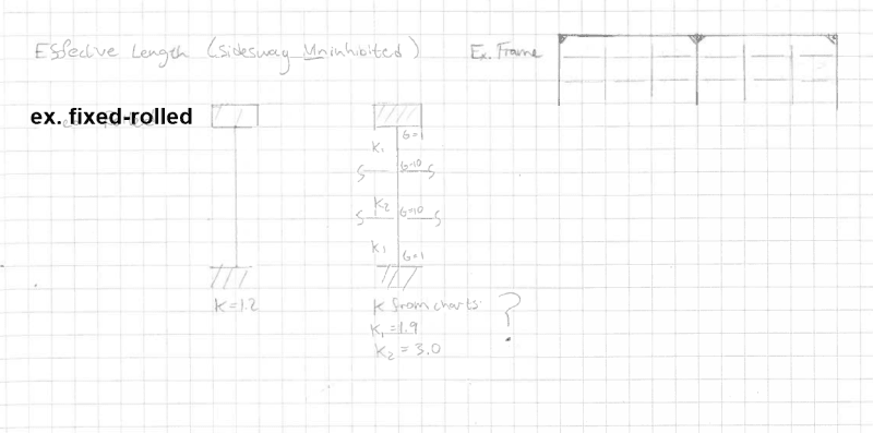
..or would I just ignore the intermediate members completely if they are all pinned and use the entire length of the column with K=1.2?

I feel that's your path forward with respect to the equivalent length method. It's simple and very commonly done that way.

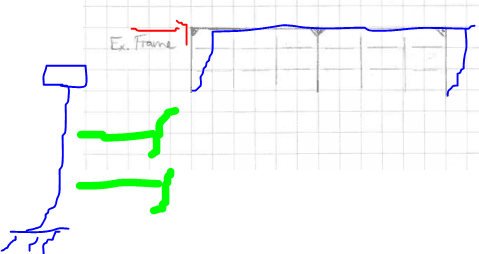
The intermediate floor members probably will have a minor bracing effect but:

a) I expect that would be of so little value that it would not justify the extra effort.

b) That bracing effect may be subject to various assumptions that may render it somewhat unreliable.

A way to test this would be to model everything and apply only your lateral loads to the frame. If meaningful forces develop in the intermediate beams, then they probably do some real bracing. If the forces developed in the intermediate beams are trivial -- as I expect that they would be -- then the bracing effect of the beams will also be trivial.

One way to think of this is:

1) Anything that constrains the deformation shape of the buckled frame will do something to brace the frame.

2) A minor impact on the shape of the buckled frame implies a minor bracing effect.

The direct analysis method is an expeditious tool for design in the hands of a skilled designer. That said, I often see the method applied like this:

a) Model everything, k=1, modifiers per the method.

b) Accept the results, whatever they are, without thinking about them. Let every damn thing offer some amount of bracing to every other damn thing.

A nice feature of the equivalent length method is that it forces to the designer to think about what is actually going on in the structure and to be deliberate about what is being used for bracing.

I feel that a direct analysis method buckling check should always be validated by some manner of equivalent length method check. If the system is too complex for those two methods to be reconciled, I would take that as evidence that the bracing system being used may be too complex to be practical. One doesn't want to be designing a column in Chicago to be reliant on some diagonal kicker out in Phoenix. Stability is too mission critical to allow its specification to be so laissez faire.
 
The book below is my favorite treatment of the effective length method. Of the course of ten pages, the author derives the alignment charts for pretty much all practical cases.

Plus, it's Galambos. That's like having Tiger show you how to swing a club.

c01_l5pptv.jpg

c02_qznevx.jpg

c03_czk8bz.jpg
 
As a side note, I think that's the only text I've seen that does the B[sub]1[/sub] / B[sub]2[/sub] method. It looks like you can view it on academia.edu. I won't vouch for the legitimacy of the document or it it's legit.

I saw something in there about stepped columns, which in this case is probably unwise, but there's also treatment of "restraint from adjacent spans" for beam buckling, which is analogous to the restraint from the less-stressed portion of the column above for the columns. I lost it so I don't have a page number.
 
If using effective length make sure you add the load on the pinned columns to the frame column load to check frame buckling. The moment frame has to stabilise the pinned columns.
 
Ok, the beam restraint from adjacent spans approach, for any future readers of this thread, is at "6.4.1 Example 6.3 Effect of Restraints from Adjacent
Spans on Beam Stability", p. 258.
 
Maybe this is not a question directly related to this thread, but it's related to the topic of stability.
There is a difference in terminology between the US and Europe so I'll try to explain it as simply as possible.
Imagine two vertical elements, one is stiff and the other is flexible (e.g. a column and a wall) connected with a rigid horizontal element (e.g. RC slab). Both are fixed at the bottom.
Wall is stiff enough to brace the column (reduce its lateral deflection by 80%, or a similar rule), but the whole structure is sway sensitive, i.e. P-Δ effects (global second order effects) are significant and can not be ignored (I think that is called Q in the US, we call it alpha in Europe... Q = alpha = H*h / (P*Δ) < 10).
Is the buckling length of the column 0,7*height or is it 2*height?
In other words, when determining buckling lengths is the total stiffness of the structure important or is only the relative stiffness of the two elements important?

Because in Europe we call braced something that has a reduced deflection, sway sensitive something that has large P-Δ effects and we also have a sway type deformation shape and a non-sway deformation shape.
In US if I understand correctly you do not distinguish between the first two, i.e. if it is braced it also has small P-Δ effects and vice versa.

This is quite confusing.
 
Well, I think that's fine.

In the U.S. P-Δ ("P-large delta") is associated with movement at the top of the column, relative to the bottom, so a "story displacement" if you like, a column that is fully braced shouldn't experience "much" P-Δ. P-small delta is distortion that increases moment inside the story.

P-Delta_a2mukw.jpg
P-small_delta_kefy90.jpg

(yea these pictures are from EnerCalc documentation. Let's move on).

What you're getting into is treatment of "leaning" columns, that are designed with an effective length of 1 that are treated as pin-pin whereas other columns in the frames are designed with larger K factors and additional adjustments due to the leaning columns.

A Practical Approach to the "Leaning" column, Geschwindner, AISC Engineering Journal, 4th quarter, 1994.

This is a pretty abstruse topic, but Geschwindner is at least an on-ramp, should you wish to delve into it. It gets pretty arcane pretty quickly.
 
Thanks for the paper - yeah, everything related to stability is very mathematical. I need the version for dummies.
But what is the difference between a leaning member and a braced one? The braced member also "loads" the bracing structure. Is it just the fact that a braced member can have an even shorter buckling length, while a leaning member can only have 1,0?
 
I suppose a braced one isn't depending on a bracing effect from the diaphragm and the frame columns. A leaning or Lean-on would.

Unless you had some kind of moment restraint, a braced column would be 1,0 same as a leaning column.

I think if you're looking for the source of some of that notation, it's probably via Bill LeMessurier. I'm not overly current on steel design, particularly this issue, the code has moved away from K factors, into a more "requirements of the analysis" approach. The AISC commentary might be of some use on the topic.

 
@Hardbutmild How does a column being braced affect European design requirements? I mean the case you mentioned where it still deflects enough to be a sway frame.

For your wall & column case first you need to check sway stability. This is done by adding sway capacity of wall and column (K>1) and comparing to sum of axial load. Then check wall and column individually for nonsway with K<=1. Use K=1 when a column is braced by a beam rather than a strut.

 
Column being braced means that lateral force is not resisted by that column I guess... the bracing system takes all the lateral load. But stability is not my strong suit so maybe I'm wrong.

Smoulder said:
Then check wall and column individually for nonsway with K<=1
This is what always confuses me. How can a wall be nonsway? How can it deflect to have a nonsway shape? I feel like it will only be able to sway like a cantilever. What is restricting its deflection at the top?
 
You're probably right for wall/column case. Total sway capacity is a lot less than the wall's non sway capacity so it sways first. Or buckles out of plane. The maths will prove this. But a wall could nonsway in plane if it it braced by a bigger wall or core and doesn't buckle out of plane first. Pretty rare case I think.
 
Status
Not open for further replies.
Back
Top