Eng-Tips is the largest engineering community on the Internet

Intelligent Work Forums for Engineering Professionals

Effects of Intermediate bracing on effective length of large cantilever 2

Status
Not open for further replies.
Jul 23, 2019
4
0
0
CA
Hi,

I'm working on a temporary beam that will cantilever 20 meters, I'm looking for information regarding the effective length to use. Most publication only discuss the restraint condition at the tip and the root, but what effects do adding intermediate bracing have on the effective length. Its a built up beam 2500mm deep. I've read Galambos guide to stability design criteria for metal structures but there is no discussion regarding the effect of intermediate stiffeners.

Any guidance or information is appreciated.
 
Replies continue below

Recommended for you

for me, the post is not quite clear since you first say that you are looking for the influence of intermediate bracings (i.e. discrete restraints which prevent LTB) but then refer to the the influence of intermediate stiffeners. which one is it? as far as i know, the presence of (full depth web) stiffeners does little to influence the critical length, although I am thinking of an I beam...not sure how applicable this is for your case. i may be wrong but i think there is a post around here which tackled the influence of stiffeners and went quite in depth into it.

in general, the critical length, directly related to the elastic critical moment of the member is not that straight forward...cantilever results in increased complexity. built up section 2500mm deep even more complexity...add discrete lateral restraints and I imagine it would be difficult to find guidance or similar examples. 20m is also a very large span.

i suggest you post a sketch and additional info in which you detail overall dimensions, load type and magnitude and your built up cross-section geometry. it would definitely help with getting more precise opinions.

overall i would suggest that the most straightforward way to analyze your problem would be to do a linear buckling analysis, probably based on a shell model of your actual cross section. you can then directly use the critical moment calculated, or use it to back calculate the critical length.
 
I agree with the fact that putting a stiffener in does not constitute a restraint.

Depending on your code, for a valid restraint for flexural loads you either need to laterally restrain the critical compression flange (prevent sideways/lateral movement), or prevent twist of the cross section (or both). A stiffener by itself does nothing to achieve either of these.

Your code should apply directly to this situation. There is nothing special required.

Is it an isolated beam, or are there a series of beams running parallel?
 
Sorry, I meant to write intermediate bracing. I plan on making a FEM and running a bucking analysis but was wondering if there were methods to check the models by hand. I'll try to post a sketch shortly.
 
Treat each section of the beam between restraints as a separate segment for evaluating the strength. Its no different to say a simply supported beam with a restrain to midspan. Your code should be letting you treat this as two discrete lengths with a factor based on the moment shape within half the beam and using half the beam length for the effective length x some multipliers based on type of restraint afforded.

If you post the code you are working to people can provide further specific examples?
 
I imagine the fact that it's a cantilever doesn't matter unless you have an unrestrained end which probably is only applicable for the last segment at the tip. Put it this way, the first segment into the cantilever with multiple braced segments doesn't know its part of a cantilever. So same rules apply, I'm not familiar with the Canadian code, but every other code I've had experience with deals with it in a similar (this) manner.
 
Agent666 said:
Depending on your code, for a valid restraint for flexural loads you either need to laterally restrain the critical compression flange (prevent sideways/lateral movement), or prevent twist of the cross section (or both). A stiffener by itself does nothing to achieve either of these.

Huh? Unless I'm missing something the critical flange here is the top, tension flange.
 
I don't think I said it was either flange, but the compression flange is usually the critical flange, whether its the top or bottom flange depends on the direction of the loading.

For a cantilever tip though you need to restrain both flanges, only doing the compression flange isn't sufficient for the restraint to be effective, as the tension flange is still unstable.

 
As I understand it there is only one critical flange. Hence the name. My understanding and what the definition that is commonly found is that the critical flange is the flange that will deflect/[move laterally] the furthest if restraint is removed. For a cantilever this is normally top flange.

MIStructE_IRE said:
Why would the top flange be critical if its in tension? The tension flange won’t buckle
The beam buckles the tension flange deflects. Either way the critical flange is the top tension flange.

Agent666 said:
I don't think I said it was either flange, but the compression flange is usually the critical flange, whether its the top or bottom flange depends on the direction of the loading.
One common exception is cantilevers where the top flange is critical. Which is the tension flange.

Agent666 said:
For a cantilever tip though you need to restrain both flanges, only doing the compression flange isn't sufficient for the restraint to be effective, as the tension flange is still unstable
The critical flange is the top flange. So if you are wanting to increase the buckling load that is where you should be restraining first.


I welcome views that contrast with the notion that the critical flange is the top flange. But it isn't exactly something I've made up. It is codified, can be recognise by buckling analysis or playing at home with a ruler.
 
human909, once you restrain the tension flange, then the compression flange then becomes the critical flange, hence the need to restrain both flanges at the tip of a cantilever as I noted for a valid/effective restraint. Both are critical in a sense. Otherwise I totally agree with what you are saying apart from this subtlety.
 
Your first statement seem to go against the underlying definition of a critical flange. Could you please elaborate on your definition of the critical flange? Oh and as far I can tell restraining the critical flange. The top tensile flange in a cantilever, will vastly increase the buckling limit of the beam and will in most cases be sufficient.

Again I'll happily be proven wrong if we want to got further than semantics. But from my reading of the AS code and buckling analysis does support my contention.

That said I've seen plenty of good posts from you in these forums so I am more than happy to admit that I'm incorrect. If you can show why. Codes don't hold the answers to everything but they are a strong pointer in the right direction.
 
Its noted in the commentary from memory (of NZS3404 at least), and our codes are basically the same except we have the seismic stuff and better slenderness limits, and you guys have the block shear stuff which our code doesn't codify. Otherwise its 99% the same. I'll see if I can find it and post back the clause.

I don't think you are wrong with your definition of the flange that wants to move the furthest necessarily. It's a good way to think of it, its just once you grab hold of the tension flange, the compression flange still wants to do its buckling thing like it would in a non-cantilever. Its not fundamentally different in that respect just because its a cantilever.

 
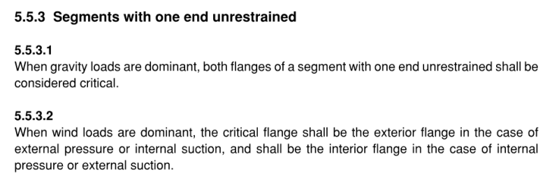
Here you go, from NZS3404
Capture_rxpth1.png

Capture_sirhyq.png


This is taught to everyone in University here as a fundamental concept. I note in AS4100 however, it doesn't say this last bit about both flanges which is surprising. But its a real effect backed by research and needs to be considered. You Aussies are usually stealing our stuff, surprised you have not stolen this yet [glasses].

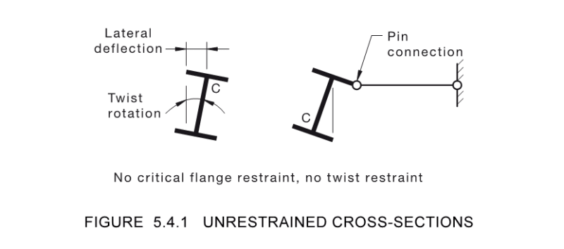
If you think of it like this, if you put a 'L' restraint to the tension flange of a simply supported beam, then it does nothing for the compression flange (see figure below from the AS4100 code) I hope you would agree? i.e. a 'U' restraint (EDIT - as far as the critical flange is concerned)!

This is the exact condition at the end of the cantilever isn't it if you only laterally restrain the tension flange? So I believe it covers the requirement in AS4100, its just not spelt out clearly/specifically like it is in NZS3404 so perhaps people don't pick up on it over the ditch in Aussie? Does that satisfy you?

Capture_g3odwk.png
 
Thanks Agent666. :)
You mostly have highlighted the differences in our understanding. From what I can see there are differences in our codes and the NZ code is more conservative here.

Agent666 said:
This is taught to everyone in University here as a fundamental concept. I note in AS4100 however, it doesn't say this last bit about both flanges which is surprising. But its a real effect backed by research and needs to be considered. You Aussies are usually stealing our stuff, surprised you have not stolen this yet
Cheeky. [rednose] But I won't dispute it. (I do find it interesting that the NZ code redefines what is a critical flange (aka both) but that is semantics rather flawed engineering.)

Agent666 said:
If you think of it like this, if you put a 'L' restraint to the tension flange of a simply supported beam, then it does nothing for the compression flange (see figure below from the AS4100 code) I hope you would agree? i.e. a 'U' restraint (EDIT - as far as the critical flange is concerned)!
Agreed.

Agent666 said:
This is the exact condition at the end of the cantilever isn't it if you only laterally restrain the tension flange?
No. I don't believe so because the tension flange is the critical flange. Aka, the flange that will deflect the most. Aka, the flange that will require the stiffest restraint.

Agent666 said:
So I believe it covers the requirement in AS4100, its just not spelt out clearly/specifically like it is in NZS3404 so perhaps people don't pick up on it over the ditch in Aussie?
The thing is that it IS spelt out clearly. But just contrasts to NZS3404.
AS4100
"5.5.3 Segments with one end unrestrained
When gravity loads are dominant, the critical flange of a segment with one end unrestrained
shall be the top flange."


Regarding what is actually good engineering. Well the NZ approach is no doubt more conservative. Whether the AS approach fails to properly consider compression flange buckling is the next question. My 'gut' feeling the compression flange in an normal cantilever isn't going to buckle readily with the tension flange restrained and twist restraint at the point of maximum compression.

But 'gut' feelings don't cut it. And I'll need to do some proper calculations or resort to other people's to try to answer it.


Again thanks Agent666. I'm still curious about this and happy to delve deep to prove myself 'wrong' or 'right'.


(I certainly have seen many cantilevered steel members without bottom flange restraints. I have designed such cantilevers myself in the past. I'd be happy delve more into this, and I am currently doing so.)
 
human said:
No. I don't believe so because the tension flange is the critical flange. Aka, the flange that will deflect the most. Aka, the flange that will require the stiffest restraint.

Once you restrain the tension flange (say an 'L' restraint), then the tension flange cannot move laterally. Then the compression flange becomes the flange that will move the most (you seem to imply its not going to move, but it is still subject to instability. I really don't know how to explain it any clearer. You're getting hung up on the critical flange forever being the tension flange, and its not the case in the view of our code at least and my understanding of how things fail.

Apply your critical flange criteria once again after restraining the tension flange, by AS4100's definition your cantilever then becomes restrained at both ends and the criteria is its the flange that then moves the most which is the compression flange. If I get time in the next day I'll do a mastan2 model to prove the impact of restraints one way or the other, I'm not disputing the fact that the tension restraint might do something, but the figure with the unrestrained section is pretty clear in interpreting what is going to occur when thinking about it from a "first principles" approach. Other codes round the world treat it in a similar manner, whether this reflects the true behaviour or is conservative I'll leave to the code writers.


Status
Not open for further replies.
Back
Top