Continue to Site

Eng-Tips is the largest engineering community on the Internet

Intelligent Work Forums for Engineering Professionals

  • Congratulations SSS148 on being selected by the Eng-Tips community for having the most helpful posts in the forums last week. Way to Go!

Effects of Intermediate bracing on effective length of large cantilever 2

Status
Not open for further replies.
Jul 23, 2019
4
Hi,

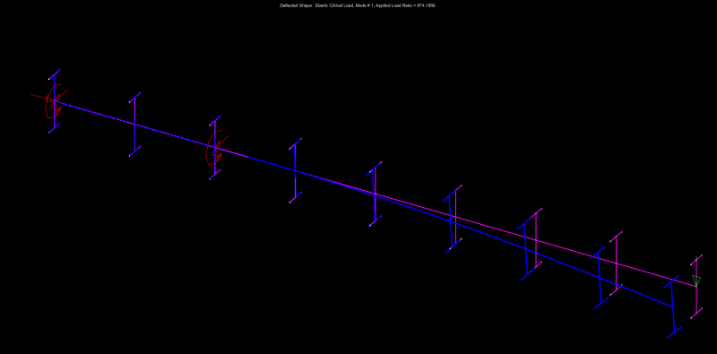
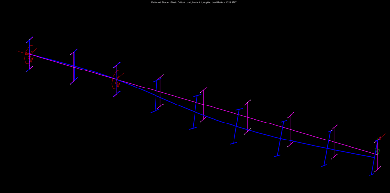
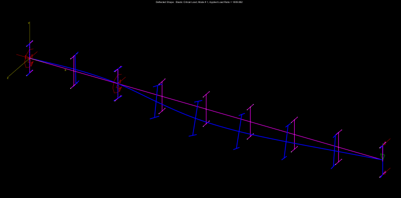
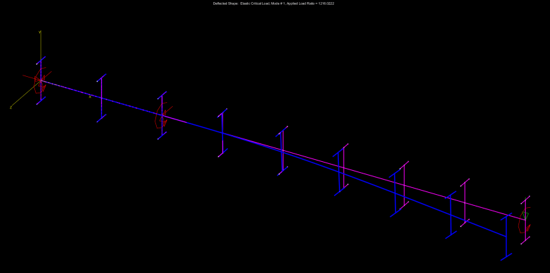
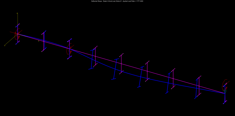
I'm working on a temporary beam that will cantilever 20 meters, I'm looking for information regarding the effective length to use. Most publication only discuss the restraint condition at the tip and the root, but what effects do adding intermediate bracing have on the effective length. Its a built up beam 2500mm deep. I've read Galambos guide to stability design criteria for metal structures but there is no discussion regarding the effect of intermediate stiffeners.

Any guidance or information is appreciated.
 
Replies continue below

Recommended for you

Agent666 said:
You're getting hung up on the critical flange forever being the tension flange
I'm not hung up on it. Simply by some definitions it is. (aka AS4100 as quoted)

Agent666 said:
Once you restrain the tension flange (say an 'L' restraint), then the tension flange cannot move laterally. Then the compression flange becomes the flange that will move the most (you seem to imply its not going to move, but it is still subject to instability. I really don't know how to explain it any clearer
You've explained that quite clearly. But the thing is, by the definitions previously referred to the critical flange is "The critical flange at any cross-section is the flange which in the absence of any restraint at that section would deflect the farther during buckling." Restraining the critical flange doesn't make the other flange the critical flange under this definition!

Agent666 said:
Apply your critical flange criteria once again after restraining the tension flange, by AS4100's definition your cantilever then becomes restrained at both ends and the criteria is its the flange that then moves the most which is the compression flange.
No see above. And it isn't my definition. It is AS4100.

Like I said it seems the discussion has devolved into semantics about the definition of the 'critical flange' and variations in codes. I think we are both interested in the true behaviour rather than simply comparing differences in codes.
 
I may have lost track in the back and forth about exactly what the discussion is about, but the AU code doesn't permit subdivision of FU or PU segments due to intermediate lateral (only) restraints. There must also be full or partial twist restraint so that both flanges are at least elastically-restrained. Or you design for the full FU/PU length.

If the cantilever tip has F or P restraint, it will be an FF/PP/FP segment for buckling design. See the last two rows of AS4100 Table 5.6.1. The critical flange will then be the compression flange.

Edit: so you essentially have to know the restraint conditions before deciding which is the critical flange.
 
If this does end up in mastan, can it be the case of:

- cantilever (for vertical loading)
- point load applied at the tip: bending moment = P*L
- lateral-rotational restraints at both ends (ie loaded point is restrained as well as the rigid support)
 
@canwesteng good point. i dont know what code op is using but in eurocode the inelastic part is accounted for through the imperfection factors in the chosen buckling curves...
@op remember to brace the beams by taking the restraining forces to a bracing system or similar. in other words, remember not to just brace the two beams between themselves, as theoretically they can both buckle in the same way at the same time.
 
Regarding the two parallel beams case. If providing twist restraint, then its my understanding that you can link the two beams with members perpendicular to the span with end conditions the achieve the cross section twist restraint then this still achieves restraint (it's not dependant on preventing lateral deflection of the critical flange. You need to either prevent twist or lateral deflection, not necessarily both. Though many practical arrangements obviously achieve both.

If you simply link the two beams say with a pin ended strut but don't prevent the lateral deflection of the critical flange (by say adding some plan bracing) then this doesn't meet the fundamental requirements for a restraint. A common example of this that people always seem to incorrectly take is considering each and every purlin as providing restraint when those purlin have no load path for the accumulation of the restraint force (for example beam is free to deflect about minor axis unless the purlin connect the something that isn't moving (like a stiff wall or something similar)).
 
human909 said:
I think we are both interested in the true behaviour rather than simply comparing differences in codes.

I believe that I may have something to offer on this front. I believe that thinking about which flange moves the most is definitely to head in the right direction. However, I think that it's even better to be thinking about the related concept of where the point of LTB rotation lies vertically. It's also useful to keep in mind that LTB is not really about compression flange buckling per se but, rather, the flopping over of the entire cross section to a position that would exacerbate deflection and move the applied loads closer to the ground (potential energy reduction which governs most natural things). Thinking about LTB in terms of compression flange buckling is a useful concept that will steer one in the right direction the vast majority of the time. But not all of the time.

Consider the two most common examples:

1) Free cantilever with no effective lateral or torsional bracing at the tip. The point of LTB rotation is below the bottom flange and LTB is the flopping over of the cantilever tip. Therefore, the most effective location for LTB bracing is at the top/tension flange which allows your bracing to act at the greatest lever arm.

2) Cantilever with both lateral and torsional bracing at the tip which is, coincidentally, is the best kind of cantilever by far. Now the cantilever tip can't flop over so it's very different. Instead, it would be a location between brace points where the cross section would have to flop over. Here the point of LTB rotation is above the top flange of the beam owing to the compression flange's tendency to kick out laterally. Therefore, the most effective location for the LTB bracing is the bottom/compression flange which allows your bracing to act at the greatest lever arm relative to the point of rotation. As others have pointed out, there's really nothing particularly "cantilevery" about this case. It's pretty much just an upside down gravity beam with some moment at one end.

Agent666 said:
For a cantilever tip though you need to restrain both flanges, only doing the compression flange isn't sufficient for the restraint to be effective, as the tension flange is still unstable.

3) The interesting case of lateral restraint to the top/tension flange only and no rotational restraint. I would describe it like this:

a) This is, in fact, acceptable so long as it's evaluated properly. One would want a pretty compelling reason to go down this path, of course, given it's inferiority compared to other options.

b) I'd expect that the critical mode of buckling for this case would be the cantilever tip rolling over but constrained to roll about the intersection of the web and top flange. This would have greater buckling capacity than the free cantilever case but less capacity than the case where the cantilever tip is rotationally restrained. There's a method for evaluating this that I've heard termed "constrained axis buckling".

 
Agent666 said:
If providing twist restraint, then its my understanding that you can link the two beams with members perpendicular to the span with end conditions the achieve the cross section twist restraint then this still achieves restraint (it's not dependant on preventing lateral deflection of the critical flange.

This I agree with. If the cantilever tips can't flop over into weak axis bending, then that ceases to be a valid buckling mode regardless of the presence or absence of lateral restraint.

Agent666 said:
You need to either prevent twist or lateral deflection, not necessarily both.

This I do not strictly agree with. I believe that:

1) You always need to prevent twist.

2) Preventing lateral deflection, alone, is never sufficient to prevent LTB.

A simple span beam with the compression flange continuously braced laterally and rotational end restraint can actually LTB buckle. We pay no heed to this mode simply because the buckling load is so ridiculously high that it merits no practical attention. You'd have section yielding etc long before you got there.


Well phrased. Kootk. And had a similar understanding though not the confidence in my understanding to properly expressive it.

Incidentally, the cantilever I recently design and went back to review. Partly to test my knowledge and partly as a secondary check fits you description of the best kind of cantilever. Tip lateral restraint and rotational restrain on the top flange.

It becomes pretty clear that with these restraints the compression flange is going to move first. Whether restraint on this flange is necessary, I'm going to re-check when I have time.
 
human909 said:
Tip lateral restraint and rotational restrain on the top flange.

Is your rotational restraint:

1) rotational restraint of the top flange (as stated) or;

2) effective rotational restraint of the entire cross section?

It would need to be #2 to fit my definition of "the best kind of cantilever".

If it's #1, you could initiate a buckling mode that starts of as web sidesway buckling at the cantilever tip.

This is probably just semantics but, then, semantics are a big deal in these discussions. It may well be that your top flange rotational restraint is also whole section rotational restraint (stiffeners etc).

 
KootK said:
This I do not strictly agree with. I believe that:

1) You always need to prevent twist.

2) Preventing lateral deflection, alone, is never sufficient to prevent LTB.

Swinging the pendulum the other way a bit, I would say that:

3) There are many practical situations in which providing lateral, translational restraint of the compressed flange takes LTB off of the functional table but;

4) Where #3 is the case, the lateral restraint is really provided as a means of restraining one particular mode of twist.

5) Interestingly, it would seem that rotation restraint is always the stronger form of bracing. This, given that translational restraint will generally eliminate one mode of twist while leaving others in play (usually of no practical consequence). Rotational restraint, by comparison, takes LTB completely off of the table for a particular unbraced length.

 
Ok for what its worth, I found the results of doing a simple case in mastan2 quite interesting to quantify relative effects. It showed a rotational restraint at the tip wasn't a hell of a lot better than the unrestrained case, and by far the best benefit gained is by preventing the lateral deflection of both flanges (which also prevents twist).

Considered effects of warping, analysis based on elastic critical buckling load (i.e. doesn't require any modelling of initial imperfections, file size blows out to Gigabytes if you do this for some reason). Geometry is setup so elastic buckling occurs, i.e. no inelastic buckling occurs.

Obviously you would still need to apply the code 'curves' to get a real code capacity which is the codes way of dealing with initial imperfections, residual stresses (all 2nd order effects basically). For example in AISC, you would work out the stress due to the buckling moment, and then run it through the normal flexural torsional buckling equations using this value.

Similarly for AS4100/NZS3404 (Which I'm more familiar with) you'd run it through the procedure in clause 5.6.4, the value coming out of your mastan2 analysis is M_ob. To work out alpha_m you need another model that is setup to give you the reference buckling moment (the constant moment case which is equivalent to use of an alpha_m of 1.0). Work out M_oa once you have alpha_m, then proceed to work out alpha_s like you normally would. M_bx = alpha_m*alpha_s*M_sx. Job done.

File attached, just play with the fixities on the cantilever tip to see the relative effects. Note that the I-section shapes are just there as a visual aid to visualise the deflection/rotation behaviour in the buckled shape and to provide approx modelling of restraint location.

All cases have arbitrary vertical point load at tip. Exact value of buckling capacity isn't important, the relative ratios is the point I'm reviewing here. i.e. if you do xxxx restraint then elastic buckling capacity increases by a factor of yyyy relative to the unrestrained case!

Keep in mind this is all relative to the actual section and geometry being used and isn't a hard rule to be applied to all situations.

Following cases were looked at:-
CASE - (BUCKLING LOAD FACTOR) RATIO - SCENARIO

Case 1 - (874) 1.000 - unrestrained tip (no restraints)
Case 2 - (1329) 1.521 - top flange lateral restraint only at tip
Case 3 - (1810) 2.071 - top and bottom flange lateral restraint at tip (note also prevents twist)
Case 4 - (1190) 1.362 - bottom flange lateral restraint only at tip
Case 5 - (1216) 1.391 - Twist restraint only at tip
Case 6 - (1777) 2.033 - Twist restraint and lateral restraint to top flange at tip (Basically effectively similar to Case 3 restraints)

CASE 1
case1_-_no_restraint_mwmolz.png

CASE 2
case2_-_lateral_restriant_top_flange_ci1qxj.png

CASE 3
case3_-_lateral_restriant_top_bottom_flange_q96udu.png

CASE 4
case4_-_lateral_restriant_bottom_flange_hghhwn.png

CASE 5
case5_-_twist_restriant_at_tip_hdloxn.png

CASE 6
case6_-_twist_restriant_and_top_flange_lateral_restraint_at_tip_evxcod.png


Hopefully that highlights the relative importance/differences in the application of different types of restraints and adds some credence to the restraining the tension flange only argument, and slightly higher capacity if restraining both flanges laterally.

I think it effectively shows that using either lateral restraint, or twist restraint achieves the same result (1.4-1.5 times in this demonstration), and that adding both twist and lateral restraint improves things further.

Finally if you are interested in mastan2 they have free stability fun modules self teaching material on their website that I highly recommend working through at your own pace as it's very useful for teaching the basics of what does and doesn't affect stability and the basis of how the code curves are derived. It's based on AISC, but can easily be worked through using any other code for comparison.
 
KootK, Australian & NZ codes are setup on the basis of either requiring lateral or twist restraint. You don't always need lateral restraint as you noted.

Hopefully the outputs above demonstrate they are relatively similar in their effect. Most practical scenarios you usually have both though, and I got a reasonable increase in the buckling load by applying both, relative to only one type.

NZ/AU codes deal with the whole section twist restraint vs flange only twist restraint through the use of a Fixed and Partial type of restraint that can involve slightly different scaling for the effective length used. For most cases they are considered the same though.

From our code for example, makes it pretty simple to classify requirements, some types have classifications on what you can consider a moment connection/pin or stiff/flexible member, etc so you can apply it to practical arrangements:-

Capture_f0lzop.png
 
Agent666 said:
KootK, Australian & NZ codes are setup on the basis of either requiring lateral or twist restraint. You don't always need lateral restraint as you noted.

I'm not sure that you've properly digested the point that I've attempted to make Agent666.

I wasn't saying that you sometimes don't need lateral restraint; I was saying that youalways need twist restraint. Lateral restraint can certainly be effective but my point is really that the root cause of it's effectiveness is that it prevents twist.

In the most pedantic and semantic of ways, my beef was really with the emphasized part of the statement below which, in my mind, implies that twist restraint is optional. And, of course, it's not optional. The only question is how you obtain twist restraint. Roll beam vs lateral brace etc.

Agent666 said:
You need to either prevent twist or lateral deflection, not necessarily both.]

 
Steve said:
As usual, if you want the TRVTH you need to go to Australia

Any chance you'd want to direct a bro' to the parts of that doc that you consider salient? It's rather long and, apparently, printed on a Gutenberg press. I read the conclusions and there were no surprises there other than the interesting tidbit below. And I guess that's to be expected. Kinda like how the best place for a horizontal stiffener on a plate girder is NOT the center of the web.

c01_cdjglo.jpg
 
I understand in your code you might need both twist and lateral restraint. But in reality having just a lateral restraint still affords some increased resistance to buckling.

In terms of our NZ/AU code twist restraint is actually optional (I'm sure others will back me up here unless I've been taught to do it wrong for 20 years!?). We have a third Lateral restraint category that is quantified, provided its applied to the critical flange. That is the point I am making, lateral restraint in the absence of twist restraint does something (in practice and in some codes), but naturally there are some penalties involved. If you don't like the approach take it up with the code writers (I am not one). The 'L' isn't as effective, but it is still better than nothing, if I understand you correct you are implying its good for nothing in your code, but it isn't in practice is my point, and our code takes advantage of this fact.

I mean if you like, go and prove otherwise in a rational buckling analysis and post back to prove the point one way or another. I'm happy to consider alternative views if there is some evidence.

I've demonstrated that having either one on its own has effectively the same effect on buckling using the mastan2 model. Increases of 1.4-1.5, of a similar magnitude, and a definate difference between only having twist restraint and twist and lateral restraints together.

From our code, perhaps this confirms our definition, maybe its considered semantics though.
Capture_lixj6s.png
 
You're still not hearing me Agent666. I'm not arguing that translational restraint is ineffective. I'm arguing that, in reality, all translational restraint really IS rotational restraint. See the sketch below for one example. That's how translational restraint works for LTB: it restrains rotation about a point somewhere in space. There is no such thing as LTB restraint that is not rotational restraint because, fundamentally, the name of the game is to keep the member from flopping over and increasing it's deflection. Lateral LTB restraint, somehow in the absence of twist restraint, simply isn't a thing.

Agent66 said:
If you don't like the approach take it up with the code writers (I am not one)

I have little interest in what anybody's codes say, including my own. Blind monkey code following is for lesser mortals. I play in the fundamental principles sandbox or not at all.

c01_l0ma5z.jpg
 
Yeah I get your point (now apparently), its potentially decreasing the rotation rather than completely preventing it for a cantilever (hence requirement in NZ at least to restrain both flanges).

I was incorrectly interpreting what you were saying that you required physical twist restraint (as part of your physical restraint) in addition to lateral restraint requirement, but you're essentially saying its a by product of laterally restraining the section that twist is perhaps reduced or eliminated. See we got there in the end [2thumbsup].

I was working/interpreting in terms of the code or any definition "rotational restraint" prevents all twist. Its either rotational or lateral from a definition/classification point of view, but fundamentally the twist is but one part of the complex fundamentals in increasing the buckling capacity, warping and residual stresses all play a role as well as the torsional stiffness.

In case 2 I posted, the twist rotation is still there you will observe at the point where I restrained the tip, even though the critical tension flange is restrained laterally only. This goes back to the compression flange still being unstable in this state and wanting to kick out.

To play devil advocate I'm curious how the following observations sit with your theory regarding the reduction of twist?
If I observe the reported twist along the member at the tip it's actually 3+ times higher at the tip when you add the lateral restraint than with the unrestrained section:-
Case 1 with unrestrained end: x_twist = 0.0002218
Case 2 with top flange lateral restraint only: x_twist = 0.0007423

Twist is only one part of the complex web of elastic buckling, warping stiffness, torsional stiffness and residual stresses all play a role. To boil it down to just twist reduction is perhaps overly simplistic.

If I still don't get it we should move on! The poor OP's had his thread well and truly hijacked at this point!
 
KootK said:
Any chance you'd want to direct a bro' to the parts of that doc that you consider salient?

It's all good stuff, but Figures 5-8 tell the story pretty quickly. Note that the wording in this document regarding translational-only restraint is as used by Agent666 (and I think most texts on the subject) rather than your own (ie lateral restraint is also rotational). I prefer to keep to the common language rather than redefining; it did take several posts for the two of you to get on the same page.

The bit I was really pointing out is that the translational-only restraint ('L' restraint in A/NZ terms) does increase the buckling capacity of the resulting FL cantilever but our codes don't permit this increase to be used. The segment would be classified as FU for design. The ignored increase in capacity is almost double in most plotted cases for tip restraint at the top flange.

The optimum full-restraint location plotted on Figures 3 & 4 (which you highlighted in the conclusion) wasn't any real surprise. If you're going to introduce an additional restraint, you should make it so you have two segments each with shorter effective length than the total length of the cantilever. For tip load, the restraint should be closer to the tip, while for distributed it should be closer to the support.
 
Status
Not open for further replies.

Part and Inventory Search

Sponsor