Continue to Site

Eng-Tips is the largest engineering community on the Internet

Intelligent Work Forums for Engineering Professionals

  • Congratulations waross on being selected by the Eng-Tips community for having the most helpful posts in the forums last week. Way to Go!

Elbow fitting question 5

Status
Not open for further replies.

Ultganon2437

Mechanical
Jun 19, 2021
8
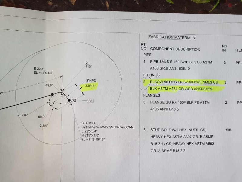
Hi I had a question in the image below. Is that setup possible with a Long Radius 90 deg elbow? Of course the elbow would have to be cut down in order to match the degrees but the thing is that a subcontractor is saying that a Long Radius elbow will not work given the length 3-9/16" that they would need Short radius 90 elbows instead. This is entirely new to me so if someone could please explain how this works or why a long radius elbow is unable to help I would really appreciate it. I know this is more of a pipefitter question but I couldnt find any forums of pipefitters.
20210903_091819_afnpsn.jpg
 
Replies continue below

Recommended for you

The end to centreline distance of a 3" LR 90 degree elbow is 4.5"
The face to weld distance for the flange is 1.12"

Even a SR elbow is 3", but presumably someone has worked out that if you cut the 90 down to 60 degrees this distance will reduce a bit.

It looks a little odd because the flange is at a 50 degree angle. A decent 3D model would help...

don't know what that 110 degrees is for?

Remember - More details = better answers
Also: If you get a response it's polite to respond to it.
 
If im not mistaken I think the 110 is there to symbolize that the elbow has to be a 70 degree elbow, but like I said this is fairly new to me and I am trying to understand elbow takeoffs and stuff like that
 
It's not a well drawn iso in my opinion as it isn't clear what plane those angles are in.

110 degrees doesn't work either as what does the 60 degree figure refer to??

Anyway, you can't do it with a LR elbow that's for sure, but you would only be 1" out compared to what is being drawn.

Once you get into compound angles you can get horribly confused...

Is it that crucial?

Remember - More details = better answers
Also: If you get a response it's polite to respond to it.
 
Judging by the BOM, this is a marine application and the odd angle is likely to match the deadrise of the hull. Note the spec for class 150 flanges and sch 160 pipe.
 
Who drew this Iso? Someone at your firm? Maybe go ask them what the design intent was.

This Iso smacks of inexperience and should be rejected.

It is all over the place with irrelevant dimensions and angles. A huge redflag for me is using a SO flange on a cutback ell. This is not typical and it is unlikely they'll get it to fit up. And even if they did, with this angle you may not be able to even bolt up the flange correctly due to clearance.

The way I'm reading this, the 49.9 degree angle is the roll of the ell and the 60 degree is the cutback angle. 2-3/4" is the correct length from the CENTERLINE of the ell to the FOF in this configuration. That said I don't know what they're trying to accomplish with the other dimensions.

Reject this Iso. Make them use a Weld Neck flange, and clearly call out the ellbow's roll and cutback angle. The other dimensions are irrelevant and add confusion.

 
I hadn't spotted the slip on flange.

Not possible IMHO to do this.

Glad some one else thinks this iso is really pretty poor

Remember - More details = better answers
Also: If you get a response it's polite to respond to it.
 
Texas, if my assumption is correct, it is not practical to use weld neck flanges here. Again, the pipe is sch160 but this system won't likely see significant pressure. Slip on flanges are the norm for this case.
 
Yea this ISO is not made here, the detail design is actually made overseas and sent to us for our production team. Correct this is for a marine application. Too many angle dimensions and I am unsure as well as to what the 60 deg stands for.
 
On another note,, does anyone have an ISO that shows the correct way that the dimensions are to be represented. I am trying to learn about the angle takeoffs and stuff
 
Send a Request for Information, RFI, back to the designer & engineer requesting clarification.

have the responsible engineer & designer confirm the SO flange on fitting complies w/ specs.

the observations & recommendations by others are valid.
 
Also to for clarification this ISO pertains for a dredge ship, the pipe is for the jet water system that will clean out the hoppers so it will experience a bit of high pressure
 
Make sure they didn't drop a 0, then. Schedule 160 pipe is used in #1500 class systems. I was assuming the heavy schedule was for corrosion allowance, which is still most likely your case.
 
@TugboatEng

I'll have to defer to your expertise as I have no marine piping experience. Out of curiosity why are weld necks not used?

In my experience it is generally considered poor piping practice to use SO flanges at fittings unless there is an absolute need to save the couple inches and you cannot accomplish it any other way.

@Ultganon2437

The reason you are getting pushback from the fabricator is the extra dimensions on the drawing, one or more of these pieces of information is wrong it seems. IMO, what they need to see clearly is the roll angle of the elbow and the cutback angle. That's it. The other dimensions are irrelevant.

It is not impossible for them to make this, but my number one concern would be clearances for the stud bolts on the flange.

It is almost certain this iso was made with an automatic isogen program. They are good but not perfect and sometimes erroneous information is generated. A good piping designer will know what to remove and how to present the information in a clear and concise way. To make this iso more clear the angular dimensions should be shown with a "V" or "H" after them, to designate Vertical or Horizontal plane angles. This is kind of a tough spot to put it but with rolled piping you usually want to see a skew triangle to clearly show what plane the piping is running in. Here is an example link for the skew triangles I am talking about:
Something else to watch out for is chained dimensions on an iso. I've seen isos with total spool length of say 20' and the chained dimensions add up to 20'-1" because of computer rounding in the model and such.

Learning good piping practices takes a long time, and all the old hats are retiring or getting their positions shipped overseas.
 
I don't know if its supposed to be 1500# but the bolts are correct for 150#.

If it does end up being a 1500# flange then this configuration will definitely not work.
 
@Texas Piper, yea these ISOs are being generated using a program, we do have the 3D model of the ship that the modelers use and I think that they just extract the ISOs from there. This is not the first issue that we have had with them with the quality of their work. Why is it poor experience using slip on flanges based on your experience? And what do you mean by roll angle of the elbow? sorry for the many questions but I do want to understand this and become good at spotting their mistakes
 
Tex, welding out a butt weld sch 160 joint is quite time consuming and expensive and requires precise fit up. A slip on flange for 3 inch can be done in 2 passes. These types of systems often get welded up in place due to the imprecise nature of ship construction and allow for a lot of axial and angular misalignment prior to welding.

Another frustratingly unknown reason is that 150# flanges are available in flat face which excludes corrosion from the exterior environment but this bit of knowledge has long been forgotten.
 
@Ultganon2437

No worries on the questions, we all were new at some point.

Because SO flanges work by inserting some of the pipe into the flange body to weld it, you can run into bolt clearance issues with smaller sized tees and elbows. In addition to that it can be a challenge for the fabricators to get the flange face true to the centerlines of the elbows. If your flanges aren’t true then you’re going to have to stress the pipe/elbow to get it to mate up potentially causing leaks or flange/fitting failure. WN flanges are designed with a bevel so it mates to beveled fittings for the weld.

This isn’t to say that it cannot be done but it should only be done where there is no other option and after ensuring there won’t be bolt clearance issues. Why someone would use a SO is that the overall length of a SO after welding can be several inches less than what a WN would be. You should not use a SO for alignment issues, it’s best to use a lap joint flange.

When you say an elbow has been “rolled” you’re saying that the plane of the elbow has changed from the vertical or horizontal plane of your pipe.

Think of a clock face as a cross section of the pipe. The elbow can go straight up or down at 12 and 6 or it can go left or right at 9 and 3. If you put your elbow at say 4oclock you would be “rolling” the elbow, and THAT angle is crucial for the fabricator to know and should be shown clearly on the isos.

Buy this book: “The Piping Guide”. Read it. Study it. If I could only have ONE piping book it would be this one.

As an aside, I too very much dislike the “high value” “engineering” done by these overseas firms. Anybody with half a brain can run a piping CAD program, but it takes a true piping engineer/designer with years and years of experience to know the how and the why. Drafting and designing plant piping was an art form before CAD came along.
 
Tex, a lot of design in these systems is left up to the pipe fitters themselves. You would be horrified at what gets passed on to customers. Failures on these types of systems rarely result in safety issues or prolonged downtime so the bare minimum is done to get the ship out of the warranty period. Once shareholders are in the picture it's a race to the bottom, especially when profit is viewed on an annual basis.

It's very common to see special trimmed bolts or captive bolts installed prior to welding. I really hate it when they use socket head screws and you don't even have room to get an Allen key in there.
 
Thanks for the Book, ill be looking into it. I have been trying to learn using youtube videos but there are not many english speaking videos on these subjects.

When you say to think of it as a clock in which it can move in any direction do you mean the whole elbow moving up/down/side to side or the angle in which the elbow will sit inside? So even though in the 3d model it looks like it works it doesn't necessarily mean that it is feasible in the real world?, when it comes to the dimensions aspect of it.

 
Status
Not open for further replies.

Part and Inventory Search

Sponsor