Continue to Site

Eng-Tips is the largest engineering community on the Internet

Intelligent Work Forums for Engineering Professionals

  • Congratulations waross on being selected by the Eng-Tips community for having the most helpful posts in the forums last week. Way to Go!

Elbow with extra bevel 2

Status
Not open for further replies.
Replies continue below

Recommended for you

Ok. It could be a bad casting/forging geometry, but within acceptable margins (Too thick, that is.) Or it might be poorly cut.

Assume the ID of the elbow is a perfect circle of diameter = ??? (Verify this, by the way).
What is the thickness of the wall at the upper tangent, introdos, lower tangent, extrados?
Is the beveled surface truly flat, or does it wave back and forth?
If the beveled surface is flat, does the other beveled surface lay 90 degrees to the first?
At the second surface, what are the same four thicknesses?
 
That is perfectly normal for a large elbow. It is called a secondary bevel, and as mentioned above, it is put there because these fittings are typically thicker than required. The welding does not have to be completed all the way to the secondary bevel, only the primary bevel.
 

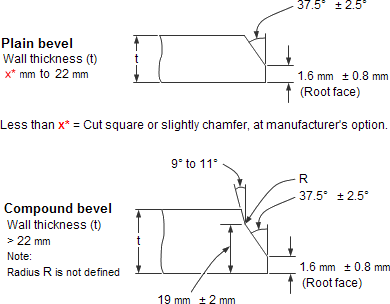
bw_bevels_compound_plijs9.gif


Piping Design Central
 
Given that the "secondary bevel" is both at a bigger angle than the primary bevel (opposite to what gator shows) and is rather variable in nature (much thinner on the outer edge) leads me to go with racookpe's post.

Looks like a fairly thick elbow so you can probably dress it up a bit or reject it.

Have a look at table 12 of ASME B 16.9 and then work out if it passes or not. Personally I don't think it is and it should be rejected.

Remember - More details = better answers
Also: If you get a response it's polite to respond to it.
 
Gator provides a good illustration. Since we are talking about 10" sch 120, t = 0.844 (21.4 mm), only the plain bevel illustration applies. The note "less than x = cut square or slightly chamfer, at manufacturer's option" means that the manufacturer can chamfer the bevel larger than 37.5 deg, at the point of 0.844", which is exactly what we are seeing in the photograph. This is also what is being illustrated in Table 12 (a) of ASME B16.9
 
It looks like the purpose of the secondary bevel in this case is simply to give the primary bevel a defined geometry and tolerance to match the bevel on the pipe and yield a clean symmetrical weld. It removes the problems caused by loose tolerance in wall thickness of the elbow.
 
Weld End Preparation at Unequal Wall Thicknesses

In most piping systems there are components such as valves, castings, heavier header sections, and equipment nozzles which are welded to the pipe.

In such instances the heavier sections are machined to match the lighter pipe wall and the excess thickness tapered both internally and externally to form a transition zone.

Limits imposed by the various codes for this transition zone are fairly uniform.

The external surface of the heavier component is tapered at an angle of 30° maximum for a minimum length equal to 1.1/2 times the pipe minimum wall thickness and then at 45° for a minimum of 1.1/2 times the pipe minimum wall.

Internally, either a straight bore followed by a 30° slope or a taper bore at a maximum slope of 1 to 4 for a minimum distance of 2 times the pipe minimum wall are required.

The surface of the weld can also be tapered to accommodate differing thickness. This taper should not exceed 30°. It may be necessary to deposit weld metal to assure that these limits are not violated.

Below some tables with acceptable design for unequal wall thicknesses acc to ASME B31.8

 
Further to BMR's post, could it be that the Sch. 120 elbow was available/cheap/fast to get and it's actually going to be installed into a lighter wall piping system? Is the other end not* similarly bevelled hinting that it may be a (strange place for) spec change?

And it may be an optical illusion, but the "secondary bevel" sort of looks like it's uneven around the circumference, which would be really odd.

* added word, 'not*
 
The secondary bevel looks uneven because the wall thickness is uneven. Without the secondary bevel the primary bevel would look uneven, and this would make welding more difficult.
 
The secondary bevel looks uneven because the wall thickness is uneven.

That is exactly right.

This elbow appears to have been hot formed, the result of which is a thicker wall thickness at the intrados and a thinner wall at the extrados.
 
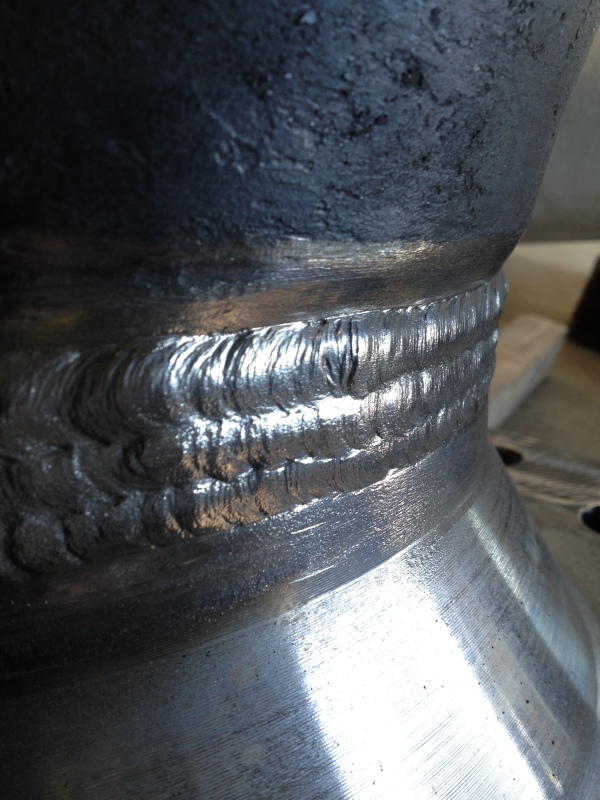
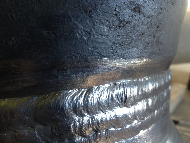
This is how it looks after welding. Taking in account that the medium it's H2S, I am more worried. The bevel between the weld and the elbow in some part it's very sharp, so in this case it's possible to be a stress concentration point.
IMG_0263_fkxuqb.jpg

IMG_0272_cuymgw.jpg


Best regards.
 
Nothing in those pictures looks off or ill to me. If you are concerned with stress raisers at a sharp point, you can grind them smooth or blend grind them.
 
OK give us the whole story and you might get a more complete answer.

All we know is the elbow is 10" sch 120.
Design code?
material?
Mating element
Wall thickness / schedule?
material?

My suspicion is you're welding a sch 120 elbow to something thinner or the vendor has given you an elbow thicker than sch 120 in the body so has machined off the "excess" or you actually need something thinner.

Remember - More details = better answers
Also: If you get a response it's polite to respond to it.
 
We asked about actual casting/forging geometry (roundness, wall thickness, wall thickness variation, etc.) earlier and got nothing. No dimensions.
 
It is called an OD transition. Fittings manufacturers make their fittings thicker to provide reinforcement in critical areas like the intrados in an elbow, crotch in a tee, etc. You can either do it two ways. One way is to add the extra thickness on the outside of the fitting and you will have an O.D. transition. The other way would be to add the extra reinforcement on the inside of the fittings, which is called an I.D. transition. I'm sure you have seen fittings with an inside transition.

The main reason manufacturers go with the OD transition rather than the ID transition is when they want the thru bore of the fitting to be as close to the I.D. (piggability issues).

This is perfectly normal unless you're Kinder Morgan.
 
its perfectly normal, but let the radiographic interpreter know.
 
Status
Not open for further replies.

Part and Inventory Search

Sponsor