RealSaladsamurai
Mechanical
Hi All - I have been researching this one for a while. I have read the Femap help and read many posts on the subject. I am almost there, but need a little more help.
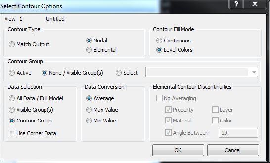
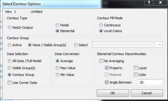
There are many options under the 'Select Contour Options' menu that seem contradictory to me. My experiments lead me to the same conclusion. Below are 2 screenshots: the Left has the NODAL radio button activated and the Right has the Elemental radio button activated. I have requested that corner data be computed by Nastran. Here are my questions/comments. Any insight is greatly appreciated.
1) Plotting Nodal Contour; Corner Data = OFF; Data Conversion (DC) = Average:
I believe that I am getting stress values at the nodes that are calculated by averaging the centroidal stresses of the elements connected at that node (the 'average' takes into account the size of the element).
2) Plotting Nodal Contour; Corner Data = ON; Data Conversion (DC) = Average:
I believe I am getting stress values that are computed directly at the corners by Nastran. No centroidal data is used and the corner values are averaged together.
3) Plotting Elemental Contour; Corner Data = OFF; Data Conversion (DC) = Average; Element Contour Discontinuities (ECD) = Property:
I get the exact same thing as in (1) above.
4) Plotting Elemental Contour; Corner Data = ON; Data Conversion (DC) = Average; Element Contour Discontinuities (ECD) = Property:
I get the exact same thing as (2) above.
Does this all sound correct? So case 1 is really an elemental contour and case 4 is really a nodal contour. So it would seem that the "Element Contour Discontinuities" should not be available for case 4. But it is and so it gives me the impression that we are not averaging across properties. But since it is really a nodal plot, I think that we are averaging across properties. And so the settings are somewhat misleading. Or at the very least very confusing.
Any thoughts on this? I have been spinning my wheels for a while now. Thanks for reading!


________________________
FEMAP v11.1.0
MSC Nastran v2013
There are many options under the 'Select Contour Options' menu that seem contradictory to me. My experiments lead me to the same conclusion. Below are 2 screenshots: the Left has the NODAL radio button activated and the Right has the Elemental radio button activated. I have requested that corner data be computed by Nastran. Here are my questions/comments. Any insight is greatly appreciated.
1) Plotting Nodal Contour; Corner Data = OFF; Data Conversion (DC) = Average:
I believe that I am getting stress values at the nodes that are calculated by averaging the centroidal stresses of the elements connected at that node (the 'average' takes into account the size of the element).
2) Plotting Nodal Contour; Corner Data = ON; Data Conversion (DC) = Average:
I believe I am getting stress values that are computed directly at the corners by Nastran. No centroidal data is used and the corner values are averaged together.
3) Plotting Elemental Contour; Corner Data = OFF; Data Conversion (DC) = Average; Element Contour Discontinuities (ECD) = Property:
I get the exact same thing as in (1) above.
4) Plotting Elemental Contour; Corner Data = ON; Data Conversion (DC) = Average; Element Contour Discontinuities (ECD) = Property:
I get the exact same thing as (2) above.
Does this all sound correct? So case 1 is really an elemental contour and case 4 is really a nodal contour. So it would seem that the "Element Contour Discontinuities" should not be available for case 4. But it is and so it gives me the impression that we are not averaging across properties. But since it is really a nodal plot, I think that we are averaging across properties. And so the settings are somewhat misleading. Or at the very least very confusing.
Any thoughts on this? I have been spinning my wheels for a while now. Thanks for reading!


________________________
FEMAP v11.1.0
MSC Nastran v2013
