Continue to Site

Eng-Tips is the largest engineering community on the Internet

Intelligent Work Forums for Engineering Professionals

  • Congratulations cowski on being selected by the Eng-Tips community for having the most helpful posts in the forums last week. Way to Go!

Embed Connection Dowel Action

Status
Not open for further replies.

Brad805

Structural
Oct 26, 2010
1,518
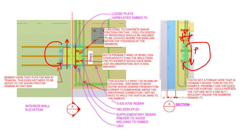
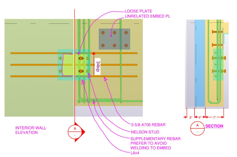
I am in the midst of designing shear connections (below) for a precast concrete project that will rely upon dowel action. The example below is the lightest load. I am interested to hear other engineers approach in a case like this. I know there are many details others will prefer, but this is what I have been asked to evaluate. I will include some screenshots from the NLFEA analysis when I am satisfied with the results. I am still testing different interface material models.

Options:
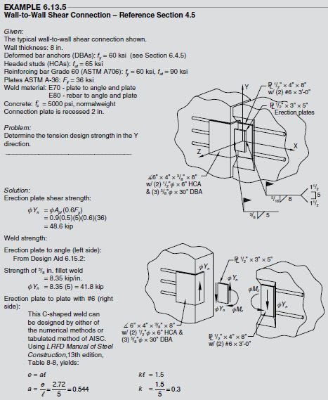
1. Problem is similar to PCI (7th Edition) example 6.13.5. That example does not really address dowel action in my mind.
2. Shear friction
3. CEB-FIP Model code 2010 section 6.3.4 shows a methodology to estimate dowel action based on estimated slip values.
4. CEB-FIP Bulletin 43 section 8.2.3 outlines methods to predict the capacity based on dowel action.
5. Vintzeleou and T. P. Tassios paper from 1986. STUDY
6. Other?
7. Load tests. Time will not permit.
8. STM

The project is in Canada.

DOWEL_ACTION_Q_u2fkfu.jpg
 
Replies continue below

Recommended for you


The worked example at PCI (7th Edition) example 6.13.5 is for Wall-to-Wall Shear Connection..In your case, apparently a sandwich facade is connected to shear wall..
You may use shear connection to support the wall element as per PCI (7th Edition) example 6.13.5 and add a stability connection at the bottom of PC wall to the slab similar to Fig. 6.13.1 Typical precast concrete connections.((b) Double-tee flange connection to spandrel or wall panel )
wall_to_wall_shear_conn_qwa0km.jpg


If you provide mor info. ( some excerpts of structural plan , precast element, RC wall system etc..) you may get better opinions..
 
Thanks HTURKAK. I am not overly surprised about the feedback. If you search the CPCI (Canadian Version of PCI) for "Dowel action", you will find zero matches. In ACI-318-19 that same search results in 5 matches. There does not seem to be consensus on the topic. I was hoping for some from the EU/AU or NZ to chime in as I have found more research from those countries. Koot has discussed this quite a few times.

That is the example. The design of the dowels I am interested is not complete in my mind, but I am reluctant to use references from the other countries. I hired a review engineer and I need to defend the design. The initial suggestion was to use HCA since one can design it per CPCI. I do not accept that idea as I have seen how those fail.

Additional details:
1. These are composite panels. We will be using non-composite connectors. I have designed thousands of those. The exterior skin does not participate in supporting the load.
2. The lintel in this case is 58" tall and spans 18'-0".
3. Lintel supports open web steel joists spanning 20'-0". Atop the joists we have a 4" concrete deck slab. I am not the EOR.
4. Lateral support is provided via a floor slab connection approximately 12" above the connection point. That will provide support, but we are expected to design our connections assuming it does not.
5. Lintel has a top connection to the wall, but is not intended to support vertical loads. That is to avoid it participating in the later
6. Wall has the same skin thicknesses. It has lateral support at each floor and bears on a CIP footing.
7. Load noted is the factored load from all applied loads.

 
I suspect that you've kind of cursed your own thread here in a way similar to what Agent666 often does: you've made your own, extensive knowledge of the subject so apparent that it becomes rather intimidating for folks to respond for fear of looking foolish in comparison. Fortunately, I have a very high tolerance for humiliation.

My thoughts below. Something that I struggle with mightily for things like this is trying to account for a connection being loaded in a bunch of different ways, and resisting via multiple, disparate mechanisms. The story that I'm telling below involves:

1) Shear, moment, and torque. Short sentence; big implications.

2) Some load being resisted via a shear friction path and some via the HCA as anchorage.

I don't have much to offer you by way of rigorous solutions to that complexity. Hopefully you'll find some value in what I've posted in spite of that.

c01_bcx4a0.png
 
I appreciate that Koot. Thinking about my question again, it was far too general. While I have done a lot of research into the topic at this point, I am not sure it helped or led to more confusion. We have used a lot of these in the past, but some of the details have always bugged me. I have a couple others where the shear is more like 65kip, and I could not convince them to use some JVI products where simple STM methods work well.

I will post some of the calcs from those references and the model pics when I have time.
 
Status
Not open for further replies.

Part and Inventory Search

Sponsor