Eng-Tips is the largest engineering community on the Internet

Intelligent Work Forums for Engineering Professionals

  • Congratulations waross on being selected by the Tek-Tips community for having the most helpful posts in the forums last week. Way to Go!

End face as secondary datum feature for runout - redundant?

Status
Not open for further replies.

Burunduk

Mechanical
May 2, 2019
2,335
0
0
IL
In runout examples 7-61, 7-63, and 12-2 of Y14.5-2018, the primary datum feature establishes the axis of rotation and constrains 4 degrees of freedom, thus stopping the relevant rotations and translations to allow the tolerance zone limit the feature. The secondary datum feature is an end face, not applying any rotational constraints to the part relative to the datum reference frame. The translational constraint applied by the end face has no relevance, since runout doesn't control location in the axial direction. Then what value does the secondary reference add?
Of the three figures, I can only see how it contributes in defining the limited area for check on the cylindrical feature in 12-2, but not useful for the cone control.

BTW, speaking of 12-2 is it just me or there are multiple errors with how the tolerance zones and limited variations are shown?
 
Replies continue below

Recommended for you

To me it looks like just a warning to avoid situation when feature may become primary when fixtured.

You can do it - doesn't mean you must do it.

If you are confident it's not going to happen, you only identify just one feature like in 12-3 or 12-4.


"For every expert there is an equal and opposite expert"
Arthur C. Clarke Profiles of the future

 
In 7-61 it is to position the datum targets on the part. Without the part would be free to slide axially.
7-63 has the same need - to axially position where the datum targets are and their extent axially.

Same interpretation on 12-2 is to unambiguously establish the axial limits on the tolerance, at least for the one associated with a chain line.

 
CH, if there is a concern that the end face might become the primary unintentionally, why not avoid referencing it altogether unless it is intended as primary?
 
3DDave, then why not employ the principle outlined in 7.24.10 and figure 9-16?
The note would state:
WHERE ONLY DATUM FEATURE A IS REFERENCED, DATUM FEATURE B IS INVOKED ONLY TO RELATE THE TARGETS THAT ESTABLISH DATUM A.
 
That's a lot of words to replace a symbol and a reference. That note undermines the point of having a symbolic system to replace notes.

Why not eliminate that note? It isn't necessary and adds another layer to interpreting the Feature Control Frames in an atypical way. Instead of being explicit in the Feature Control Frame, it says use those references even when they aren't in the Feature Control Frame. All those same references still have to be evaluated so it doesn't simplify any evaluation, including inspection. It doesn't even make the drawing any cleaner.

There is a great benefit - it also undermines Model Based Definition as there is typically no uniform means to combine symbolic and textual controls on datum feature reference logic.
 
3DDave,
Does it mean you would recommend referencing A,B,C instead of just A in the perpendicularity FCF in figure 9-16?
 
If those references are required to completely immobilize the orientation of the part, then yes - it's also why I think parallel and perpendicular need to be dropped in favor of angularity. The example (again, Y14.5 is a by-example standard) is to demonstrate a note that is not necessary. It's a bad practice, but the bigger and more bloated the standard is the more opportunity to sell training. And it lets more people keep their pet idioms.

I'd also note that this is a view-dependent tolerance zone example, a graphical depiction of the sort the model based definition group has been working to stamp out. They got rid of the offset line for unequally disposed profile tolerance indication, they need to get this next

It will take a while for the committee to realize that they need a mechanism in the feature control frame to specify which datum plane is used as a basis, like [angularity ref A (of) 0.25 <each element symbol> |A|B|C]

[A|B|C] establishes the constraints required to hold the part, while ref A tells which portion of the coordinate system is the intended one.

This would allow

[angularity ref B (of) 0.25 <each element>|A|B|C] or
[angularity ref C (of) 0.25 <each element>|A|B|C]

if that could somehow be important. And look - the bonus of more training material sales.
---
This note reminds me of the sort of result that comes from group-think, turning an ad-hoc decision into policy. Bob (not his real name) won't be placated over something and some pacifier is the only thing that will shut him up. The rest of the group sighs and goes along with it because otherwise Bob will refuse to sign the drawing, release will be late, and the program will be set behind schedule. Bob feels great because he got his way and the rest of the group now has to add this trash note for the rest of eternity because it is now the rule and will be there long after Bob is worm food, for reasons of "Being Consistent."

See "Bob" is the guy with the icy water, punishing everyone.
 
3DDave,

3DDave said:
This note reminds me of the sort of result that comes from group-think, turning an ad-hoc decision into policy. Bob (not his real name) won't be placated over something and some pacifier is the only thing that will shut him up. The rest of the group sighs and goes along with it because otherwise Bob will refuse to sign the drawing, release will be late, and the program will be set behind schedule. Bob feels great because he got his way and the rest of the group now has to add this trash note for the rest of eternity because it is now the rule and will be there long after Bob is worm food, for reasons of "Being Consistent."

See "Bob" is the guy with the icy water, punishing everyone.

We have Bob in our organization. Just saying.
I agree with your assessment.
You go along to get along.
 
Good points.
Thanks.
One remark, the MBD group has not been acting to stamp out practices related to "view dependency" (in terms of 2D drawings) such as orientation tolerances applied to line elements of a surface, straightness, and profile of a line. Instead, they provide solutions for direction indication for the same type of tolerances when applied to the model (they are called "direction-dependent tolerances" in Y14.41). These solutions are representative line elements being part of the model annotation, associative with the tolerance, or association between the direction dependent tolerance and a specific axis of a coordinate system (such associations are indicated to the user querying the model by a visual response - for example, the axis is highlighted when a tolerance is selected). These techniques do not really solve the realistic inspection-floor problems of view dependency, rather, they preserve them by making it look like everything is fine on the designer's work station.
 
Then what value does the secondary reference add?

It might be useful because if there are other callouts on the drawing that reference those 2 datums, then the inspector only needs to set the part up once.

John-Paul Belanger
Certified Sr. GD&T Professional
Geometric Learning Systems
 
the MBD group has not been acting to stamp out practices related to "view dependency"

You describe non view-dependent adaptations of otherwise view-dependent graphical depictions. Not sure what problems in particular are caused or not addressed by relating to specific orientation geometry, but that could be a separate thread.
 
3DDave said:
Not sure what problems in particular are caused or not addressed by relating to specific orientation geometry

Consider straightness of line elements on a flat surface. In the drawing, the indication of tolerance zones direction is the view. On the model, the indication is supplemental geometry in the annotation.
On a physical part, the only way to achieve repeatability in that direction, is to use a Datum that is not part of a starightness tolerance.


3DDave,
So you are in favor of a solution equivalent to the Intersection Planes of ISO 1101-2017 to be implemented in Y14.5?
 
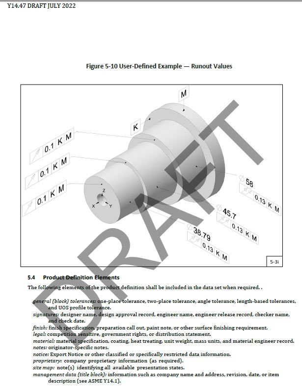
New draft of Y14.47-202x is at least consistent with the theory. Doesn't it?
(Model Organization Practices; Engineering Product Definition and Related Documentation Practices)

Y14.47-DRAFT_-_Copy_v0da67.jpg
 
greenimi -- that example has the surface feature as the primary datum, so it makes sense. The OP question was about the value of having the surface datum be secondary (where it might not seem to add any value to the runout idea).

John-Paul Belanger
Certified Sr. GD&T Professional
Geometric Learning Systems
 
Status
Not open for further replies.
Back
Top