Continue to Site

Eng-Tips is the largest engineering community on the Internet

Intelligent Work Forums for Engineering Professionals

  • Congratulations SSS148 on being selected by the Eng-Tips community for having the most helpful posts in the forums last week. Way to Go!

End plate moment connection 1

Status
Not open for further replies.

Veer007

Civil/Environmental
Sep 7, 2016
379
Hey Guys,
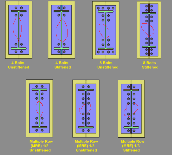
I just wonder about this one, why generally we have to separate top and bottom bolt groups for endplate connection? what if the bolt has been provided continuously throughout the web of the beam?

I knew that the top group bolts were in tension and bottom one in compression, then what was my concern is

Should not we provide bolt at the center of the web where rounded in red? so that, why?

when I have moment force and shear force, I should count on flange bolts (bolts that near to flange both above and below) for moment and web bolts for shear.
END_PLATE_576x519_suljoy.png


Thanks in advance!!
 
Replies continue below

Recommended for you

Vee0007, get a trail version of
You should be able to see the results in detail.

However the centre bolt is often provided on deep connections to not have the plate come away from the member and show a gap.

"Programming today is a race between software engineers striving to build bigger and better idiot-proof programs, and the Universe trying to produce bigger and better idiots. So far, the Universe is winning."
 
You can understand the reason by looking at the beam stress diagram due to moment - where are the maximum/high stresses located, and how the stresses vary from the flanges toward the geometry center. Also, we often design the connection using the simplification, T = C = M/d, that assumes the flanges carry the majority of the applied force, thus, that are the locations the blots bolts to be placed.
 
stresses vary from the flanges toward the geometry center

Great guess... that and the beam acts as a stiffener and the connection of the end plate is pretty stiff...

Dik
 
why generally we have to separate top and bottom bolt groups for endplate connection?

There are two reasons why we do it this way that I can think of.
1) To avoid shear / tension interaction in the bolts. For Bolted End Plate connections, the assumption is that the bolts on the tension side of the connection resist ONLY tension and do NOT contributed to the shear resistance of the connection. Likewise, the bolts on the compression side are viewed to resist ONLY shear and do not resist any tension. Not technically, true. But, it's conservative and it's convenient.

2) The yield line method is concerned with the transfer of the tension flange force into the plate and the bolts. Right? The further away from the tension flange you get, the less effect those bolts will have on the plate yield lines.
 
If you design assuming elastic behavior, the centroid of the connection is at the center.
So, bolts placed in the center there will have 0 strain , and won't contribute to the moment capacity.
 
The further away from the tension flange you get, the less effect those bolts will have on the plate yield lines.

So you can use a thinner plate in the middle?[bigsmile]

Dik
 
dik,

You can carve the middle out...
 
You can carve the middle out...
I was just jokin', but years back I was wondering what the effects of adding the end plate to only the top and bottom... not likely cost effective.

Dik
 
I was kidding too. I think its attractiveness is ease of fabrication, and ease in design. Erection may not be that easy though.
 
Veer007 said:
knew that the top group bolts were in tension and bottom one in compression,
There are no bolts in compression. Also the moment direction determines whether top or bottom bolts are in tension.

Veer007 said:
web bolts for shear.
you can't force the shear load in a moment connection to go to the web bolts only; shear is hard-headed
 
End plates at the bolts only won't align good. Full length plates can align bolt holes unless you really mess up attaching them. Partial plates top and bottom may leave one set not aligned at all.
 
So, top bolts resist tension/moment creating tension, and bottom bolts should be counted for shear, okay?

But perhaps when there a reversible load condition, the bottom bolts should be in tension, right. Am I wrong?

Thanks in advance!!
 
Sorry veer007 while I love the software I really have no idea about the way it runs offline or similar.

"Programming today is a race between software engineers striving to build bigger and better idiot-proof programs, and the Universe trying to produce bigger and better idiots. So far, the Universe is winning."
 
and bottom bolts should be counted for shear, okay?

Both top and bottom bolts are counted for shear. While the top bolts have to be checked for the combined tension and shear, the bottom bolts checked against shear only, unless there is force reversal.
 
Thanks no problem

Thanks in advance!!
 
Your last post make me clear.

But still I am not clear about the gap between bolt groups.

I thought I should not provide bolt at centre or I could count this for shear if I provided bolts at centre?

Thanks in advance!!
 
Yes, for excessive shear demand, bolts can be provide in the middle for that purpose. But, since the bolts in the middle do not contribute, or contribute very little, in resisting the bending, the additional bolts will only escalate the cost, if the bolts on the flanges are adequate to handle both (bending and shear). Note that the end plate connection is usually provided for beams with considerable amount of moment that calls for deep section, but the tension and compression are concentrated on the flanges only, so it leaves huge space in between.
 
Also, why do we need a thicker plate? do endplate yield stress need more than connection beam?

Thanks in advance!!
 
Status
Not open for further replies.

Part and Inventory Search

Sponsor