Continue to Site

Eng-Tips is the largest engineering community on the Internet

Intelligent Work Forums for Engineering Professionals

  • Congratulations GregLocock on being selected by the Eng-Tips community for having the most helpful posts in the forums last week. Way to Go!

End plate of bracket design

Status
Not open for further replies.

gojgo

Structural
Dec 15, 2016
9
We have some bracket and want to use for deck end concrete. Bracket have HSS 102x52x4.8 welded to 300x178x13 End plate. End plate have factored moment of 4.7 kN.m and factored shear of 12.2 kN. Shear will be resisted by weld between HSS and end plate. Because of moment I will have tension on anchor, those will be 23.5 kN each. Is length and width of the plate ok? How do I design plate thickness? should I use this equation:
Fy = 4*Mf/0.9*B*t^2 where Fy=300 N/mm^2, Mf=4.7 kN.m, B=300 mm, I am getting 14.46mm thick plate, is this right? do I have to check anything else? don't have any book right now with me to check.I have attached sketch. Thanks in advance.
 
Replies continue below

Recommended for you

Normally you work out your plate bending from the force of the bolt to the face of the member and then used yield lines to get you length for bending over. Recommend a quick google search for yield lines for base plates.

"Programming today is a race between software engineers striving to build bigger and better idiot-proof programs, and the Universe trying to produce bigger and better idiots. So far, the Universe is winning."
 
I agree with rowingengineer that yield line theory would be appropriate for this problem. One of the difficulties is in figuring out the shape of the yield line. It is not immediately clear. Another difficulty is in attaching two bolts in tension into what appears to be the side shell of a hollowcore slab. Before spending too much time on the first problem, let's examine whether two 23.5kN forces can safely be applied to the side wall of the slab.

BA
 
The slab looks pretty thick? I'd be using a deeper 4 bolt plate to get bigger lever arm.

No need for the bolts to be 100mm from the section either. That just makes life harder on the plate.
 
Thank you BAretired, Hilti 3/4" KCM-WF Cast-in insert required 102mm minimum member thickness and design strength is 30.1 kN in Tension for each . Do you have any material on yield line theory for steel plate for my situation?
 
gojgo:

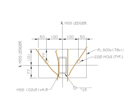
I'll have another look at it tomorrow, but I believe the yield line pattern is as shown below:

Endplate001_ffyty5.png


BA
 
That yield line pattern is too complex.

The long diagonal dashed lines will just continue to the top corners. And there will be no shorter lines.
 
Also, since the shear force will be transferred through anchor bolts in tension, shear will produce bending stress in the bolts as well.
 
I think two bolts connection lacks redundancy, unless keep the stress low. Also need to make sure that the manufacture provide capacity includes capacity reduction due to combined shear and tension.

Have you considered prying action in the design? I think I agree more with BA's yield lines, but the two short dished lines can be extended to the upper corners.
 
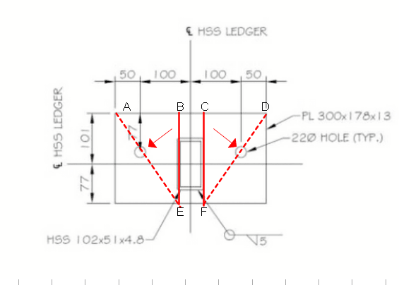
One thing I did wrong for sure was two of the arrows which are supposed to indicate the fall line are off by 180o. I will change that later.

Tomf suggests a simpler set of yield lines which look reasonable and should be explored.

EndPlateTomf_pfrzur.png


What we want to do is equate Internal Work (IW) with External Work (EW)

Assume a deflection of 1.0 unit at points B and C. The arrows indicate the fall lines which must be perpendicular to AE and DF respectively. Yield lines are shown in red. Solid lines are ridge-like; dashed lines are valley-like.

External Work
EW = Mf*θ where Mf is the factored moment and θ is the rotation, in this case θ = 1/178
EW = 4.7e6/178 = 26,404 N-mm or 13,202 N-mm for each symmetrical half.

Internal Work
Length of AE = 217mm
Effective length of BE = BE*cos(AEB) = 145mm
Let m be the resisting moment of the plate per mm
Slope of triangle ABE = 1/BE*sin(AEB) = 1/102

IW = m(217 + 145)/102 = 3.12m for each symmetrical half.

IW = EW, so 3.12m = 13,202
so m = 4,225 N-mm per mm
But m = phi*Fy*Z = 0.9Fy*t2/4 = 4,225

Solving, t = 7.91mm

Unless I've made a mistake, 8mm thickness would be enough for strength, but yield line theory does not check deflection, so some engineering judgment has to be used. A 1/2" or 5/8" plate seems to be a reasonable choice.


BA
 
I like the simple pattern proposed by Tomfh, so I'm not going to bother checking my earlier pattern. One of the problems with Yield Line Theory is that the critical pattern is a trial and error procedure.

BA
 
BA,

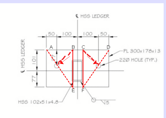
I've no knowledge on yield line design. But buy imaging the deformed shape, wouldn't the lines shown below is be more likely?

d_lz59gc.png
 
retired13 said:
I've no knowledge on yield line design. But by imaging the deformed shape, wouldn't the lines shown below be more likely?

The HSS member welded to the plate is exerting a moment on the plate, pulling points B and C away from the concrete slab where the bolts are fastened. Lines AE and DF have zero deflection for their full length. Triangles ABE and CDF remain plane with high points at B and C and sloping down to lines AE and DF in the direction of the two arrows. A yield line can't exist in a surface which remains plane.

BA
 
Just a discussion. In this situation, I prefer the failure initiate from the plate rather than bolts. So avoid the plate been too rigid. However, the stress on the upper corners of the tube can be very high though.
 
Gojgo (the OP) says the Hilti 3/4" bolts can carry 30.1 kN. That must be a pullout value because a 3/4" A307 bolt can carry a tension of 70kN. A pullout failure would tend to be sudden and catastrophic, so I agree that a plate failure is preferable, but if it is too flexible, it won't look good either.

The sketch has now been removed from the original post. I don't know why.

BA
 
retired said:
Just a discussion. In this situation, I prefer the failure initiate from the plate rather than bolts. So avoid the plate been too rigid. However, the stress on the upper corners of the tube can be very high though.

It makes sense to have the bolts a lot stronger than the plate.
 
I am not in favour of bolts anchored into the edge shell of a hollow core slab. The strength of that connection is difficult to determine, regardless of what Hilti might claim.

BA
 
7 Apr 20 00:15

I am not in favour of bolts anchored into the edge shell of a hollow core slab. The strength of that connection is difficult to determine
Agree BARetired, the wall is only 125mm thick, it will be lots of overturning moment.
 
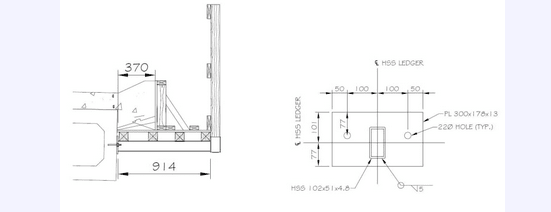
Really? It doesn't look that thick in your first sketch (see below). Where did the figure of 30.1 kN bolt tension come from? From Hilti? A concern has been raised that the plate may be stronger than bolt pullout which could result in a sudden collapse in the event of accidental overload.

OP_rwds1e.png


BA
 
Status
Not open for further replies.

Part and Inventory Search

Sponsor