Continue to Site

Eng-Tips is the largest engineering community on the Internet

Intelligent Work Forums for Engineering Professionals

  • Congratulations SSS148 on being selected by the Eng-Tips community for having the most helpful posts in the forums last week. Way to Go!

End Plate thickness Calculation

Status
Not open for further replies.

allimuthug

Civil/Environmental
Oct 5, 2014
142
End_plate_connection_ucktyw.png

Hi
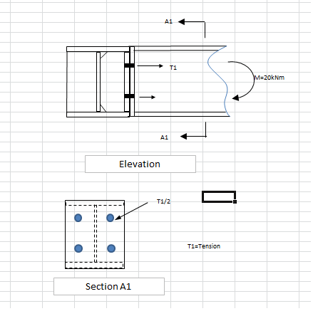
I have an End Plate Moment Connection, where there is tension in the End plate T1 From the Structural bolt.
Can anybody help me to calculate the thickness of the end plate due to tension of anchor bolt.
 
Replies continue below

Recommended for you

You need to do a yield line analysis. AISC has a design manual for flush end plate connections.
 
I believe this is covered in the AISC design guide.
1) Assume that 50% of the tension goes into each flange.
2) Calculate an "equivalent moment" that will produce that same flange tension.
3) Ad that into the regular moment. Then use the regular design guide procedures for resisting that moment.

There's nothing wrong with CanWesteng's recommendation. It works great if you only have tension. But, the case of combined moment and tension, I would use this procedure instead.
 
That looks like a shear connection to me. As Tony implies, the supporting beam likely won't resist the moment you are hoping to impart. But then, we have no dimensions.
 
Hokie - I almost said the same thing first. then I realized that he probably means for it to be designed as a flush end plate moment connection.... which is a partially restrained moment connection.

It will be a good bit more flexible of a connection, than most moment connections. But, no reason why it can't be done.
 
I often use a similar connection, but, with the left side being a mirror of the right side for transferring both moment and shear. Generally use heavier end plates to minimise prying action.

Dik
 
Referring only to the OP's detail, unless the supporting member can take the torsion, not relying on the supported member in bending to ensure stability, I would consider it a shear connection. Doing it this way can make erection simpler, but heavier plates won't help that.

But then, I wonder about where the M=20kNm came from. That is not much moment.
 
Hokie:
I often use it for plastic design where the moment is often .25*Mr... and prying action does occur... and a thicker plate is often called for, but, have a spreadsheet to fully design the connection.

Dik
 
Fair enough, but I imagine you are connecting to a column, or something stiff, not into the side of a torsionally weak wide flange beam.
 
it may initially behave as a shear conn but eventually have to transfer a portion of the torsion into the supported member in bending....to get an upper bound I would design it to transfer the full torsion into bending in to the supported member and add web stiffners to the supporting member to address the local fla bending of the supporting member .....IMHO, it is not a good conn as I suspect that there are secondary forces being developed that would be difficult to quantify.....
 
There may be little torsion involved. With clamping, the stiffness of the beam will reduce the rotation.

Dik
 
I would design it as though the centre of the pin support is the centreline of the beam in torsion. Generally the beam rotates in torsion enough to behave like a pin at this end, but then the end plates need to carry moment such that there is a continuous "beam" between supports.
 
Status
Not open for further replies.

Part and Inventory Search

Sponsor