GPTX
Mechanical
- Jun 11, 2015
- 3
Good afternoon,
I've got a very silly question.
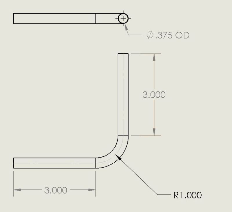
Background: My company has thousands of drawings - many of which were created without adherence to any sort of standard. Due to the time crunches and the general culture of the company many drawings get sent out to suppliers without being properly revised or sometimes even released. Drawings often end up using the default tolerances shown in solidworks (x.xxx) with an additional note called out in our title block (x.xxx = +/- 0.005). These dimensions end up on all sorts of parts - wiring, copper tubing, sheet metal with multiple bends, etc. Our suppliers have learned to deal with it and typically don't question us on the dimensions (ie: copper bender knows that when we want a piece that's 12.000" with a radius 1.000" bent to 90.00 degrees that we don't /really/ need it to be like that at all).
Unfortunately this is a huge headache for the quality department because when we inspect parts they (obviously) usually do not meet the spec.
The correct action to do would be to fix the drawings; however, nobody's got the time for that. Furthermore, lots of parts are stored in older, incompatible drawing formats (ie: inventor or even autocad) so would need to be recreated from scratch to be "fixed."
So the question is: is it accepted practice anywhere in the industry to have engineering drawing addendums? I know that they're used in the construction industry where a form is attached to a drawing saying "Zone X: A should be B." Essentially this would be a quality inspection guideline which says "Drawing XXXX: Zone X, dim 0.500+/-0.005 is allowed to be 0.50+/-0.3." This form could be quickly created & attached to the pdf (bumping up the revision a minor revision letter) without redoing the whole drawing. The added benefit of this would be that the discrepancy between the drawing & the part are documented instead of what we do now (just pretend it's not a problem).
Thanks,
GP

