Continue to Site

Eng-Tips is the largest engineering community on the Internet

Intelligent Work Forums for Engineering Professionals

  • Congratulations cowski on being selected by the Eng-Tips community for having the most helpful posts in the forums last week. Way to Go!

Engineering Post Frame Buildings

Status
Not open for further replies.

medeek

Structural
Mar 16, 2013
1,104
I'm getting ready to do an analysis of a post frame building and I am still hunting down every resource I can find to educate myself since this is the first post frame building I have ever done. I've managed to acquire a copy of the 1999 Post-Frame Building Design Manual published by the NFBA, which appears to be the defacto standard for pole building engineering. However, online I have found other misc. papers describing a "simplified" method for designing post frame buildings.

I am wondering what others typically use as their reference and what are your thoughts on the simplified methods (Don Bender and Drew P. Mill).

I've also just noticed that the second edition of the NFBA manual has now come available.


Has anyone had a chance to purchase it and compare it with the 1999 edition (First Edition)?

A confused student is a good student.
Nathaniel P. Wilkerson, PE
 
Replies continue below

Recommended for you

50% isn't as bad as I've seen some so you've got that going for you.

Have you really trimmed down your roof dead loads (I know it hurts the uplift calcs but those are easier to deal with usually). It likely won't get you to passing but it may trim a few percent off of the code check.

I would get confirmation on the post species and grade if possible that way you have an accurate capacity.

If you got this down to 120% or less I would be impressed. The existing ones don't calc out as we all have been saying the whole time.

You could knee brace the columns and it might get you enough.
 
A HF No. 1 will work, :)

Now the final piece of the puzzle...

I'm looking at the uplift resistance of a 18" dia. by 4' deep post hole backfilled with concrete. At 150 pcf the concrete donut basically weighs 934 lbs. My basic uplift from the wind combined with 0.6 of the dead loads is only 703 lbs so that works.

However, to get an additional margin I would like to include a value for the skin friction between the soil and the concrete cylinder. I'm not seeing an example of that calculation in any of the resources and texts I'm looking at.

Then of course there is the problem of the corner posts which are acting as the shearwall chords and resisting the lateral loads. They have a certain uplift which is countered by the roof and wall dead load to some extent 7.) 0.6D + 0.6W and the uplift capacity of the backfill.

In my opinion these types of structures are an engineer's nightmare. There is way too much going on with these posts both vertically and laterally. A conventionally framed structure distributes the loads far better and is easier to analyze. I've spent the entire week trying to spreadsheet this thing and I know my analysis is still far from adequate or complete.


A confused student is a good student.
Nathaniel P. Wilkerson, PE
 
So this is interesting:

If I assume a 6" deep circular collar at the base of the post (4' embedment) I then am able to take the cone of soil per 8.9.4 of the NFBA manual which is 3,893 lbs.

However, if I assume concrete backfill to the surface then all I have is the weight of the concrete in the hole minus the post area which gives 934 lbs.

Does this not seem somehow counter intuitive? Wouldn't the concrete lift some of the soil with it in a full on uplift situation?

The question is how to quantify this.

8.9.3 of the NFBA manual states that concrete backfill gives an uplift resistance of the mass of the concrete plus skin friction but then gives no further guidance.

A confused student is a good student.
Nathaniel P. Wilkerson, PE
 
The customer wants to leave the front of the carport open so I am looking at doing a sheathed kneewall brace, if such a thing exists. The idea is to create something similar to a portal frame at the front of the structure. I'm not sure how to apply any numbers to this though yet, still rolling it around with a couple of other ideas.

I'm thinking it will put a concentrated load on the corner post 4' feet down from the eave as well as a similar load on the 20' fink truss above. There is a double 2x6 top plate below the fink truss but this is not the same as a deep beam that can accommodate the bending loads.

Has anyone run into something like this before? Any suggestions?

A confused student is a good student.
Nathaniel P. Wilkerson, PE
 
The national frame building association used to put on webinars about every other month going over industry standard designs. Contact them to see if you could maybe get a copy of the slides or maybe they have one recorded. I found them to be helpful. I may have a pdf of the slides if I can find it.

EIT
 
My geotechnical expertise is pretty weak but I am guessing the skin friction between the full concrete collar and soil is insufficient to engage the available shear strength of the surrounding soil. I just looked at the new ASABE EP486-12 and it states a "device that enlarges the base" can use the uplift resistance provided by soil. The commentary include with the draft of this reference did directly state that without the enlarged base only skin friction should be considered.
 
I just found Breyer's example problem 12.8 for a knee wall brace, I will use this for a guide.


A confused student is a good student.
Nathaniel P. Wilkerson, PE
 
Just so you know... post-framed buildings are framed after the building is erected.

It's Friday...

Mike McCann, PE, SE (WA)


I wish it was a Friday for me right now. This post frame building has been nothing but grief.

The full analysis of the post frame is here for those interested:


Assuming that the structure transfers the bulk of its lateral loads to the end walls (shearwalls A and B) and the post frames on grid lines 2 and 3 do not offer any significant resistance I get a shear load of Vw = 1630 lbs, which doesn't sound like a lot.

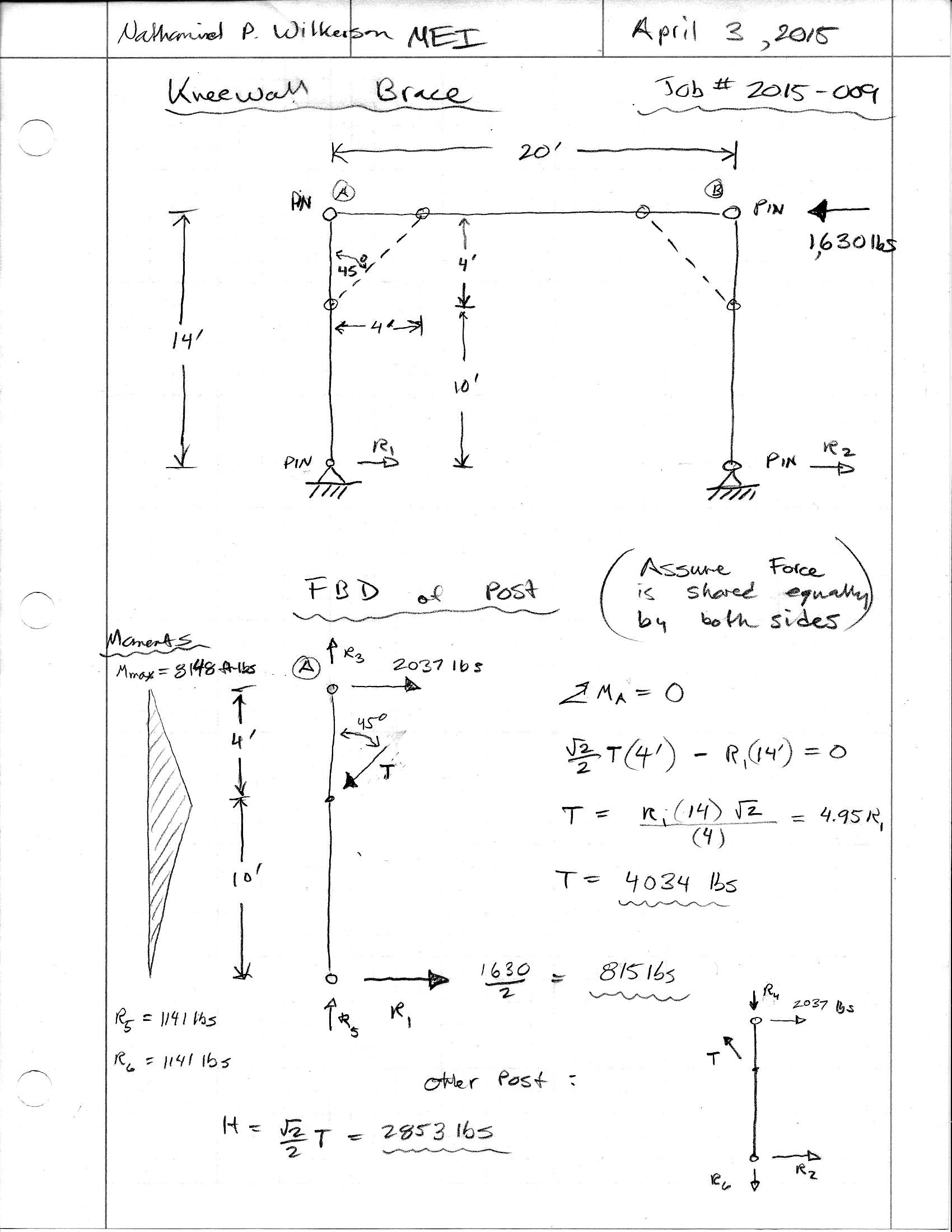
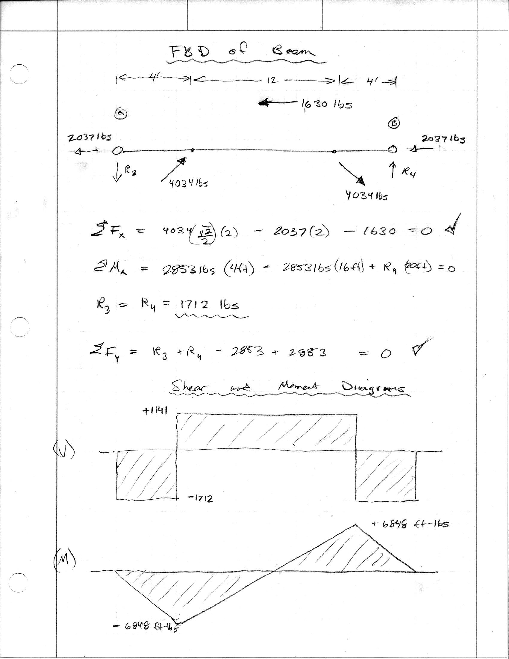
So I then run the following manual calcs to determine if a 4' diagonal knee brace will work on the one end wall:

KNEEBRACE1.jpg


KNEEBRACE2.jpg


The axial force in my knee brace is a whopping 4,034 lbs.

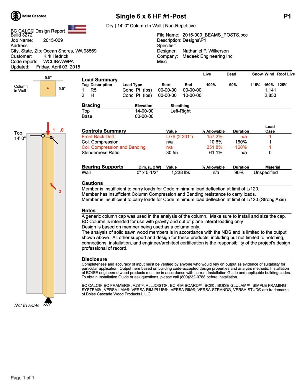
I then check to see what effect that might have on one of my 6x6 HF No. 1 corner posts:

KNEEBRACE_P1.jpg


As you can see it does not work, not even close.

The loads on the horizontal header would also require some beefing up of the gable end truss bottom chord but that can easily be arranged.

With respect to the knee brace and the corner post I don't think sheathing the knee brace will do much to decrease the bending moment in the corner post but I could be wrong. Any suggestions?

I thought of a few different solutions:

1.) Tell the client knee bracing won't work and make him install two additional end wall posts to create a 12' wide door as I originally envisioned he might do.
2.) Sister another 6x6 or even 4x6 post to the existing corner post to get more bending strength, attached the to posts with some counter sunk lag bolts and sheathing.
3.) Somehow analyze the knee brace differently so that my axial force in this member is decreased?
4.) Re-analyze the entire post frame building treating the roof diaphgram as rigid, essentially a three wall structure. The problem with this is that it doesn't really agree well with other accepted methods of assigning shear loads to post frame buildings (ie. NFBA manual etc...)

A confused student is a good student.
Nathaniel P. Wilkerson, PE
 
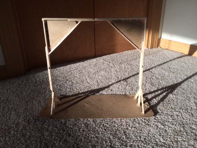
Here is the popsicle stick and cardboard analog. It helps to have a physical model to get a feel for all of the forces and deflections of the members...

KNEEBRACE3.jpg


A confused student is a good student.
Nathaniel P. Wilkerson, PE
 
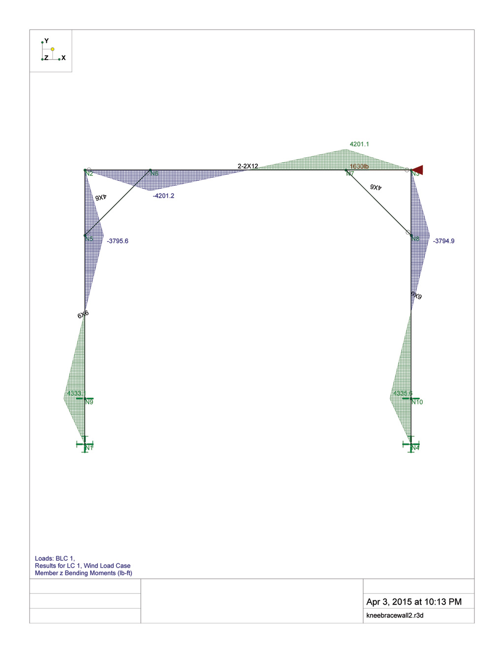
Number 3 and 4 were kind of the answer. My original analysis assumed a pin joint at the ground, this throws all of the lateral resistance onto the knee brace. In reality we have the two knee braces and the embededded posts resisting the lateral loads. When I tried to run the statics equations by hand using the pin/roller @ .7d modeling method things got too hairy for my liking so I put it into Risa3D:

KNEEBRACEWALL_MOMENTS.jpg


Actually, before I ran with RISA, I first checked to see what would happen if just the embedded posts tried to resist the load without any knee braces and assuming 815 lbs at 14 ft off the ground I get a 11,410 ft-lbs ground line moment. That certainly wasn't going to work.

Anyhow, even with the reduction in moments and assuming a DF No. 1 post the numbers are still too high. Bending wise it comes in at about 98% but then if you add in the axial and calculate the combined stress index its about 170%.

However, putting it into RISA was a good idea since I got a deflection at the eave that manually I could never have reasonably calculated. The deflection is about 2.2", which is extremely large compared to the deflection of the roof diaphragm (7/16" OSB sheathing on 24" o/c trusses). So given that I can assume a rigid diaphragm and basically throw most of my calculations out the window...

The question is now do I really need any sort of knee bracing at all. The three other walls are fully sheathed with 15/32 plywood, plenty of shearwall and stiffness and no windows or doors.

I kind of wish I knew RISA a little better, I would probably put the whole structure into it and let it figure out what component (post, shearwall, knee braces etc...) is actually taking the lateral loads.


A confused student is a good student.
Nathaniel P. Wilkerson, PE
 
I basically already was considering the diaphragm as perfectly rigid by utilizing the simplified method from Drew Mills paper. The problem with my analysis was that I was distributing the reactions from the diaphragm to the endwalls equally. Obviously this is not the case. A more realistic approach would be to look at the center of the rigidity with respect to the center of the load and proportion the shear loads to the shear walls per the example in Ch. 16 of Breyer's text. This was my final approach, the tricky part was to determine a realistic but yet conservative value for the stiffness of the endwall braced only with knee braces. Based on the deflections generated in RISA (2.2" for a lateral load of 1630 lbs, my shearwall stiffness would then be approx. 730 lbs/in or .7 kips/in. This extremely low value when input into the calculator yielded such a low lateral load that it seemed prudent to use a higher stiffness to give the knee braced wall a greater load.

I think I finally have a handle on this one but after so much trouble in making it "work" I'm left thinking that maybe there is something else that I have not accounted for that will pop up and invalidate the entire updated set of calculations.

A confused student is a good student.
Nathaniel P. Wilkerson, PE
 
Medeek -> first I appreciate your efforts in digging through all post-framed material and posting your thoughts here. Second,
The three other walls are fully sheathed with 15/32 plywood, plenty of shearwall and stiffness and no windows or doors
So you have sheathed walls? Why not just use these for your LFRS?

EIT
 
Rfreund,

There was a fair amount of discussion a while back as to whether 3-sided shear wall structures were acceptable. I'll continue to watch this thread with interest.
 
You show a pinned condition at nodes N9 and N10 of your RISA model. If this represents your ground surface, it is likely much too stiff for soil backfill. If you had a slab on grade that was constraining your post, a pinned condition may be more realistic. If you have soil backfill, I would recommend lateral springs or a fixed condition some distance below the ground surface. ASABE used to suggest a distance below the ground surface of d/3 but now they are recommending a distance equal to width of the pole. The later seems short to me.
 
The decision to go with a pinned connection was made after a phone conversation with the client. Currently the garage is a dirt floor but he has decided to pour a stemwall around the perimeter with a slab that connects to the 18" DIA x 48" concrete backfilled holes.

A confused student is a good student.
Nathaniel P. Wilkerson, PE
 
Status
Not open for further replies.

Part and Inventory Search

Sponsor