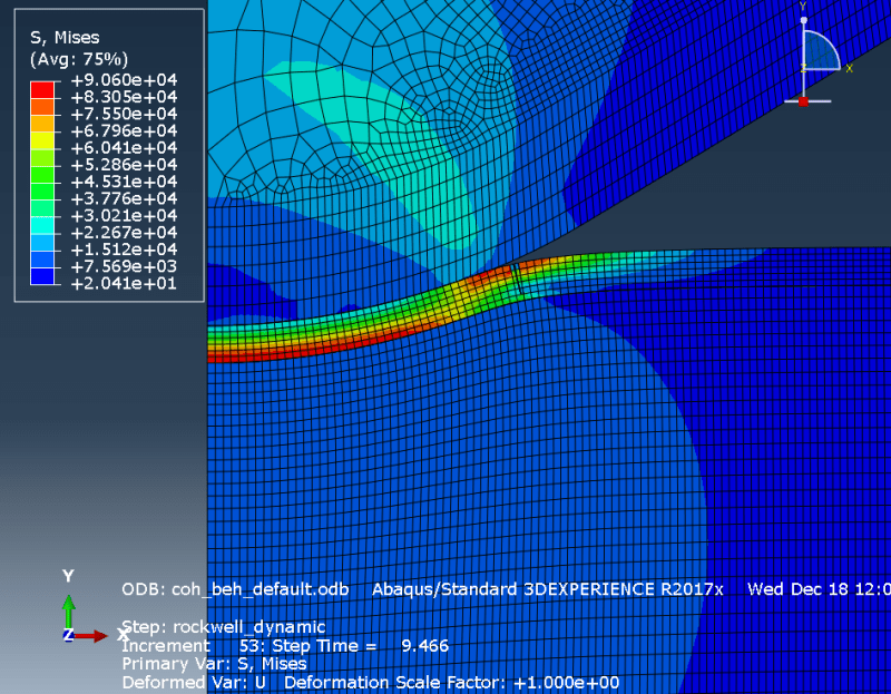
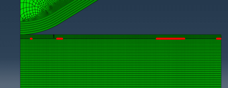
Thanks for your answer.
For the coating-substrate contact i used a Node to Surface contact with finite sliding. Do you mean the Data file? The Data file for the interaction section looks like the following:
***NOTE: DUE TO EXCESSIVE REPORTING, THE ECHO OF THE *SURFACE OPTION IS BEING
SUPPRESSED.
*contactpair, interaction=_INTERFACE_CONTACT-PROP, adjust=ASSEMBLY_VERBINDUNGSKNOTEN
*contactpair, interaction=RW_CVD, type=SURFACETOSURFACE
*surfaceinteraction, name=INTERFACE
*surfacebehavior
*surfaceinteraction, name=RW_CVD
*surfacebehavior, pressure-overclosure=HARD
*surfaceinteraction, name=TEST_INTERFACE
*surfaceinteraction, name=XFEM
*surfacebehavior
*surfaceinteraction, name=_INTERFACE_CONTACT-PROP
*surfacebehavior
*contactpair, interaction=_INTERFACE_CONTACT-PROP, adjust=ASSEMBLY_VERBINDUNGSKNOTEN
*contactpair, interaction=RW_CVD, type=SURFACETOSURFACE
*enrichment, name=XFEM, type=PROPAGATIONCRACK, elset=ASSEMBLY__PICKEDSET14, interaction=XFEM
*surfaceinteraction, name=INTERFACE
*surfaceinteraction, name=RW_CVD
*friction, sliptolerance=0.005
*surfacebehavior, pressure-overclosure=HARD
*surfaceinteraction, name=TEST_INTERFACE
*surfaceinteraction, name=XFEM
*surfacebehavior
*fracturecriterion, type=VCCT, normaldirection=MTS, mixedmodebehavior=BK, unstablegrowthtolerance
*surfaceinteraction, name=_INTERFACE_CONTACT-PROP
*cohesivebehavior
*damageinitiation, criterion=MAXS
***WARNING: THE SECOND MAXIMUM SHEAR TRACTION AT FAILURE MUST BE GREATER THAN
ZERO FOR COHESIVE ELEMENTS, SURFACE_BASED COHESIVE BEHAVIOR, OR
XFEM ELEMENTS IN 3D; OTHERWISE, IT WILL BE ASSIGNED THE SAME VALUE
OF THE FIRST MAXIMUM SHEAR TRACTION.
*damageevolution, type=ENERGY, power=1, mixedmodebehavior=BK
*surfacebehavior
*fracturecriterion, type=VCCT, normaldirection=MTS, mixedmodebehavior=BK, unstablegrowthtolerance
*surfaceinteraction, name=INTERFACE
*surfaceinteraction, name=RW_CVD
*surfaceinteraction, name=TEST_INTERFACE
*surfaceinteraction, name=XFEM
*surfaceinteraction, name=_INTERFACE_CONTACT-PROP
*boundary
*boundary
*boundary
*boundary
*boundary
*contactpair, interaction=_INTERFACE_CONTACT-PROP, adjust=ASSEMBLY_VERBINDUNGSKNOTEN
*contactpair, interaction=RW_CVD, type=SURFACETOSURFACE
*enrichment, name=XFEM, type=PROPAGATIONCRACK, elset=ASSEMBLY__PICKEDSET14, interaction=XFEM
*surfaceinteraction, name=INTERFACE
***WARNING: PLEASE CHECK TO MAKE SURE THAT THE INTERACTION PARAMETER IS USED
ON THE *ENRICHMENT OPTION FOR LEFM CRITERION OR LOW CYCLE FATIGUE
ANALYSIS.
*surfaceinteraction, name=RW_CVD
***WARNING: PLEASE CHECK TO MAKE SURE THAT THE INTERACTION PARAMETER IS USED
ON THE *ENRICHMENT OPTION FOR LEFM CRITERION OR LOW CYCLE FATIGUE
ANALYSIS.
*surfaceinteraction, name=TEST_INTERFACE
***WARNING: PLEASE CHECK TO MAKE SURE THAT THE INTERACTION PARAMETER IS USED
ON THE *ENRICHMENT OPTION FOR LEFM CRITERION OR LOW CYCLE FATIGUE
ANALYSIS.
*surfaceinteraction, name=XFEM
*surfaceinteraction, name=_INTERFACE_CONTACT-PROP
***WARNING: PLEASE CHECK TO MAKE SURE THAT THE INTERACTION PARAMETER IS USED
ON THE *ENRICHMENT OPTION FOR LEFM CRITERION OR LOW CYCLE FATIGUE
ANALYSIS.
*contactpair, interaction=_INTERFACE_CONTACT-PROP, adjust=ASSEMBLY_VERBINDUNGSKNOTEN
*contactpair, interaction=RW_CVD, type=SURFACETOSURFACE
*enrichment, name=XFEM, type=PROPAGATIONCRACK, elset=ASSEMBLY__PICKEDSET14, interaction=XFEM
*output, field, frequency=2
*output, history, variable=PRESELECT
*output, field, frequency=2
*output, history, variable=PRESELECT, frequency=10
*elementoutput, directions=YES
*elementoutput, directions=YES
*output, field, frequency=2
*output, history, variable=PRESELECT
*output, field, frequency=2
*output, history, variable=PRESELECT, frequency=10
*elementoutput, directions=YES
*elementoutput, directions=YES
SLAVE : ASSEMBLY_S_SURF-4
MASTER: ASSEMBLY_M_SURF-4
DISTANCE
NODE ADJUSTED REMARKS/WARNINGS
14463 4.00000E-10 ADJUSTED TO ( 0.50000 , 4.00000E-02).
14464 4.00000E-10 ADJUSTED TO ( 0.49800 , 4.00000E-02).
14465 4.00000E-10 ADJUSTED TO ( 0.49600 , 4.00000E-02).
14466 4.00000E-10 ADJUSTED TO ( 0.49400 , 4.00000E-02).
14467 4.00000E-10 ADJUSTED TO ( 0.49200 , 4.00000E-02).
14468 4.00000E-10 ADJUSTED TO ( 0.49000 , 4.00000E-02).
14469 4.00000E-10 ADJUSTED TO ( 0.48800 , 4.00000E-02).
14470 4.00000E-10 ADJUSTED TO ( 0.48600 , 4.00000E-02).
14471 4.00000E-10 ADJUSTED TO ( 0.48400 , 4.00000E-02).
14472 4.00000E-10 ADJUSTED TO ( 0.48200 , 4.00000E-02).
14473 4.00000E-10 ADJUSTED TO ( 0.48000 , 4.00000E-02).
14474 4.00000E-10 ADJUSTED TO ( 0.47800 , 4.00000E-02).
14475 4.00000E-10 ADJUSTED TO ( 0.47600 , 4.00000E-02).
14476 4.00000E-10 ADJUSTED TO ( 0.47400 , 4.00000E-02).
14477 4.00000E-10 ADJUSTED TO ( 0.47200 , 4.00000E-02).
14478 4.00000E-10 ADJUSTED TO ( 0.47000 , 4.00000E-02).
14479 4.00000E-10 ADJUSTED TO ( 0.46800 , 4.00000E-02).
14480 4.00000E-10 ADJUSTED TO ( 0.46600 , 4.00000E-02).
14481 4.00000E-10 ADJUSTED TO ( 0.46400 , 4.00000E-02).
14482 4.00000E-10 ADJUSTED TO ( 0.46200 , 4.00000E-02).
***WARNING: FOR CONTACT PAIR (ASSEMBLY_S_SURF-4-ASSEMBLY_M_SURF-4), NOT ALL
THE NODES THAT HAVE BEEN ADJUSTED WERE PRINTED. SPECIFY
*PREPRINT,CONTACT=YES FOR COMPLETE PRINTOUT.
I hope this will help you. As you can see, other interaction related warnings occur during the simulation.


