magrimmelprez
Mechanical
Hi! (I'm new here, sorry if I make dumb questions)
So, I am simulating a three point bending test on a human clavicle for one of my researches.
I was able to simulate a three point bending test for a different bone (mice femur) with the same boundary conditions and other properties, but for the clavicle, I get very odd results that I haven't been able to fix yet.

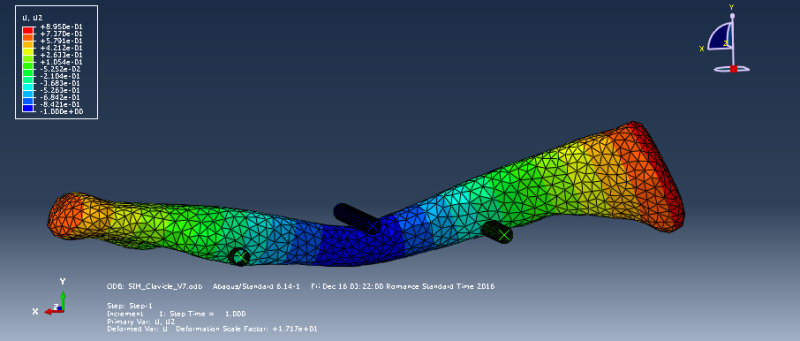
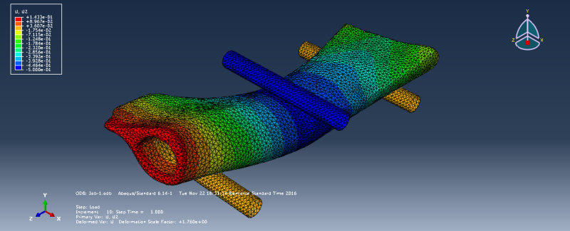
As you might see in the picture that I tried to attach, when I apply a 1mm displacement through a Loading Beam, my bone deforms, but it goes through the Support Beams and allows the Loading Beam to invade it as well.
Right now I am working with the following conditions:
My bone is meshed with C3D10, around 40000 elements.
I have an interaction property between bone and beams that is Mechanical -> Tangential Behavior and Mechanical -> Normal Behavior.
Besides, my Boundary Conditions are:
Support beams are ENCASTRE
Loading Beam can only move in y direction and has a 1mm displacement in the -y direction.
Bone: The Reference Point of my bone (a point I created in the middle) can move only in the y direction.
Furthermore, I have a Coupling Constraint for some nodes around this reference point (in the same plane) in all directions.
Should I change any of these to obtain a better solution?
As I said, I ran these same properties on a femur and I got good results. (No beams in my bone )
)

I hope I provided info enough!
Thanks in advance!
Marie
So, I am simulating a three point bending test on a human clavicle for one of my researches.
I was able to simulate a three point bending test for a different bone (mice femur) with the same boundary conditions and other properties, but for the clavicle, I get very odd results that I haven't been able to fix yet.

As you might see in the picture that I tried to attach, when I apply a 1mm displacement through a Loading Beam, my bone deforms, but it goes through the Support Beams and allows the Loading Beam to invade it as well.
Right now I am working with the following conditions:
My bone is meshed with C3D10, around 40000 elements.
I have an interaction property between bone and beams that is Mechanical -> Tangential Behavior and Mechanical -> Normal Behavior.
Besides, my Boundary Conditions are:
Support beams are ENCASTRE
Loading Beam can only move in y direction and has a 1mm displacement in the -y direction.
Bone: The Reference Point of my bone (a point I created in the middle) can move only in the y direction.
Furthermore, I have a Coupling Constraint for some nodes around this reference point (in the same plane) in all directions.
Should I change any of these to obtain a better solution?
As I said, I ran these same properties on a femur and I got good results. (No beams in my bone

I hope I provided info enough!
Thanks in advance!
Marie
