Continue to Site

Eng-Tips is the largest engineering community on the Internet

Intelligent Work Forums for Engineering Professionals

  • Congratulations KootK on being selected by the Eng-Tips community for having the most helpful posts in the forums last week. Way to Go!

ETAP UNDERGROUND

Status
Not open for further replies.

mrcheese

Electrical
Oct 4, 2007
25
I'm using ETAP underground design latest version. If I have two duck banks, one has a layer of fluidized thermal backfill, and the other doesn't, why are they coming out at the same temperatures? See attached.

in this example, Concrete RHO=30
FTP RHO = 40
Earth RHO = 200
Screenshot_2024-07-02_080743_aoxkzv.png
 
Replies continue below

Recommended for you

Butb seems the currents are different, maybe you made the calculation for constant temperature and variable current?
 
I am sorry. I use neither ETAP nor SKM. I use simply excel [Microsoft] and Neher & McGrath publication or IEC 60287-1-1 and 2-1.I prepared- by myself- some programs in Visual Basic for specific problems-duct banks and other underground cable run [for ampacity calculation].
For instance, in your sketch the conductor temperature is 47-48oC. Actually, in my opinion, it is only the temperature rise from ambient -I think 25oC Earth.
If I take the cable as single core copper 500 kcmils conductor 1 kV insulated -with out FTB- I get 202.4 A ampacity [maximum 75oC as per NEC]
According to Neher&McGrath chapter Use of a low-resistivity back fill we may use for Earth resistance formula 44a using instead of ρc the ρf of the back fill material and for the Gb factor to consider the back fill in the duct-bank dimensions. So, I got 60oC conductor temperature-that means instead of 48oC rise only 35oC rise [for 200 A load].
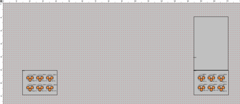
 
Seems like ETAP is not considerign the section above because you didnt define a duct in that section. Have you tired using a direct buried raceway instead? Since both RHOs of your concrete and backfill is the same, im guessing you are better off using a raceway with a 40 C.cm/W of 25x60cm.

As an additional comment, I wouldnt use 30 C.cm/W for concrete. A more realistic value is 80 C.cm/W.
 
NEC Annex B 8.2 Typical Applications Covered by Tables
[NFPA 70/2023]
Concrete = 55[oC-cm/watt].

IEEE 835/1994 Concrete: 60 °C cm/W

IEC 60287-2-1 Ed.1.2 2006-05
Table 1 – Thermal resistivities of materials
Materials for duct installations
Concrete= 1 Km/W [100 °C cm/W]
 
Status
Not open for further replies.

Part and Inventory Search

Sponsor