Continue to Site

Eng-Tips is the largest engineering community on the Internet

Intelligent Work Forums for Engineering Professionals

  • Congratulations cowski on being selected by the Eng-Tips community for having the most helpful posts in the forums last week. Way to Go!

Examples of Equivalent Dimensioning & Tolerancing Schemes

Status
Not open for further replies.

pmarc

Mechanical
Sep 2, 2008
3,227
Hi,

Throughout the years I have come to a conclusion that in general there are not many examples where changing dimensioning and tolerancing scheme from one to another would keep the geometric requirements for the system unchanged.

One example where this conclusion would not be true is changing from perpendicularity wrt A to total runout wrt A when applied to a flat face normal to datum axis A.

Another one would be a simple bushing where its ID and OD are controlled with the same +/- tolerance, and then it does not really matter which of the features will be datum feature A and which will be controlled with position or runout relative to A.

I have some more, but I would like to see what others can offer. So could anyone share some examples?
 
Replies continue below

Recommended for you

chez311,
You are right.
The inner boundary will be 4.7.
My judgement can't be trusted today :)
 
pmarc said:
greenimi,
I agree with pylfrm. These are not equivalent schemes.
I hope someone will do it earlier, but if not, I will try to post a sketch later today to show this.

pmarc,
You DO NOT have to do it today. It is for my (our) education, so do it at your luxury.

And thank you.
 
Well, if I do not do it today, I will not do it this week, so here it is:

The graphic has been made in powerpoint and it is to show one of possible scenarios. In order to be sure that none of the median points of the olive dashed lines falls outside of the concentricity tolerance zone, I modelled this in my CAD system. So you have to trust me here. Hopefully based on this it is clear that the 0.2 circularity + dia. 0.2 concentricity combo defines less stringent geometrical requirements than the circular runout tolerance of 0.2. I guess we might conclude it is because the circularity tolerance zone does not have to centered on the datum axis.
 
I am not sure what greenimi meant by formula "Total runout = concentricity + cylindricity", but I think we have to add them together.

So, using numbers from pmarc's diagram, " 0.2 (Concentricity) + 0.2 (Cylindricity) = 0.4 (Total runout) "

I have to correct myself: we may have to multiply concentricity by 2, so the formula would be " 2 X 0.2 (Concentricity) + 0.2 (Cylindricity) = 0.6 (Total runout) "

"For every expert there is an equal and opposite expert"
Arthur C. Clarke Profiles of the future

 
Hmmm... I never thought that one could think about it this way :)

greenimi, we need your clarification.
 
Judging by the Tec-Ease video greenimi linked to, CH's assumption is correct, so the green tolerance zone should be double in thickness.

Maybe this is ahead of time but the next question might be:
IF indeed the sum of cylindricity + concentricity is almost equal to tot. runout (and it does look like a good approximation), how much less accurate will it be to say that:
Coaxial position + cylindricity also equals total runout?
It is clear that position differs from concentricity as it only takes into account the UAME and no median points (that in turn depend on points on the surface) are involved, but nevertheless it's also a coaxial location control and we have cylindricity to take care for the surface anyway.
 
semiond said:
IF indeed the sum of cylindricity + concentricity is almost equal to tot. runout (and it does look like a good approximation)

In the attached graphic (that shows the same actual contour), the actual circular runout error is definitely not a sum of actual errors of circularity (0.2) and concentricity (0.2).

I trully hope that now we will not start a debate whether this fits the definition of decent approximation or not.
 
pmarc, I will certainly not be the one trying to develope a debate over approximations, I would rather discuss the CDRF concept on the new thread [wink]
 
semiond,
I did not comment in the CDRF thread yet because I think we need a "fresh blood" there. I know there are people on this forum that could contribute to the discussion in a thorough way. So be patient, please.
 
CH, pmarc and everyone,

pmarc said:
Hmmm... I never thought that one could think about it this way smile

greenimi, we need your clarification.

Full disclosure. I searched online for an explanation of why runout would qualify for concentricity (within the same value) and found Tec-Ease’s video. Then I saw that could be an “equivalency” (or at least sort of) and thought I could contribute to pmarc’s discussion. I did not go in the full details on my own question or fully judge or thinking about its implications.

Now if I am thinking about it I would go by pmarc’s first sketch and not by the second one. That’s how I would read and interpret the video and explanation from Tec-Ease.
 
Equivalent_datum_schemes_ot12t2.png


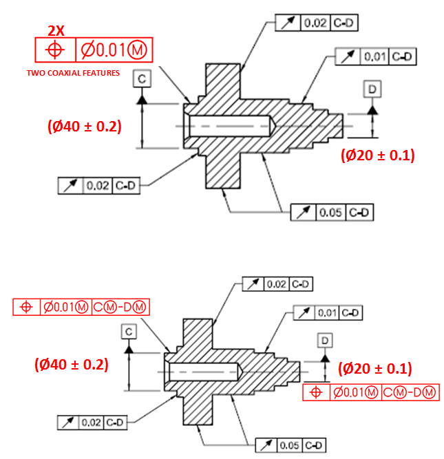
Since I do not want this thread to be extinct and also based on an earlier discussion with pmarc about examples of equivalent dimensioning and tolerancing schemes, I am posting two schemes below (I guess they are above) and questioning their equivalency.

This is what I understood from the discussion, but I also might be wrong and misunderstood previous statements.

So, here you are: are those datum schemes equivalent? If not, how to make them to have the same mathematical definition, if all possible?

I realize, might not be entirely possible, but I am tossing it out there.

Thank you for your input.
 
greenimi,

I referred back to this thread the other day too when that total runout vs. circular runout + cylindricity question was brought up. It would be nice to update this thread when someone runs across a (potential) equivalent control.

There are two things you might want to note:

1) I know what your intent is for your first scheme, however because your example has several coaxial features the meaning is somewhat ambiguous. The fact that you are referring to the two datum features is maybe implied but not explicit - perhaps something like a note "TWO COAXIAL DATUM FEATURES C AND D" or similar, however others might find that cumbersome I'm not sure.

2) In your both schemes (#1 2x pattern at MMC and #2 2x features at MMC and C(M)-D(M) at MMB) you have datums which are defined at MMC/MMB that are utilized for runout which must be at RFS/RMB. Because of this wouldn't you want to define your datums at RFS/RMB as well?

Other than the slight technicalities of my notes 1/2 and accepting that you've brought this up as just an example I would think that yes, these two schemes are equivalent as far as I can tell.

EDIT: somehow mashed that submit button before I had finished typing, oops.
 
greenimi,

I agree that the two schemes are equivalent under the assumption that "TWO COAXIAL FEATURES" means datum features C and D.

The example seems pretty strange though. A similar example would be adding a tertiary datum feature reference of C(M) to the position tolerance applied to datum feature C in Fig. 4-9 of ASME Y14.5-2009. It wouldn't change anything, and there's probably no rule prohibiting it, but what purpose would it serve other than causing confusion? You're basically creating the same boundary twice, once with the position tolerance and once with its datum feature reference.


pylfrm
 
Equivalent_datum_schemes_meuae9.png


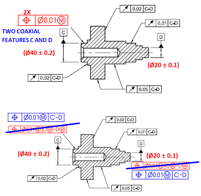
Looks like “people’s choice awards” goes to blue scheme, doesn’t it?

I assume my modified scheme (in blue) fits better the thread scope per the above comments.
 
Datum feature C and datum feature D are different nominal sizes. Maybe that's why it's best to not lump them together with the same feature control frame.

John-Paul Belanger
Certified Sr. GD&T Professional
Geometric Learning Systems
 
Belanger:
The standard seems to be OK with two features of different sizes:
Capture_ulp6ll.png

greenimi and others:
Does anyone think composite tolerance may better align features to each other?

"For every expert there is an equal and opposite expert"
Arthur C. Clarke Profiles of the future
 
CheckerHater said:
Does anyone think composite tolerance may better align features to each other?

CH,
The problem I can see with composite is the features we are trying to control are the datum features in other words are the driving features and not the driven ones.
I can see how to used composite tolerances on the driven features, but not so much on the driving ones.

The picture I used is from the standard (2009) and I've modified it to fit my purpose.

Maybe you can offer a sketch for a potential solution, I am all for learning.
 
Sorry greenimi, I don't have a solution.
I was trying to visualize for myself if your schemes are perfectly equivalent, or some slight adjustment may be needed.
It looks like it's good enough for practical reasons.
Some heavyweights of this forum could possibly have different opinion, hence my question.

"For every expert there is an equal and opposite expert"
Arthur C. Clarke Profiles of the future

 
greenimi,

ASME Y14.5-2009 does not define how datum axis C-D would be derived from RMB datum feature references. That being said, I think your two new schemes are probably equivalent. I can't think of any geometry that would meet the requirements of the upper scheme but not the lower.

I think the lower scheme from your latest image is even stranger than what it replaces though. In this case, a similar example might be adding a secondary datum feature reference of B(RMB) to the position tolerance applied to datum feature B in Fig. 4-26 of ASME Y14.5-2009. I can't imagine why anyone would want to do that. Can you?


pylfrm
 
pylfrm said:
ASME Y14.5-2009 does not define how datum axis C-D would be derived from RMB datum feature references.
Maybe not exactly "how" but many of the runout examples are utilized with self referencing RFS/RMB datums (due to the requirements of runout) and when I made my comment I figured something more along the lines of my #3/4 below. I agree the mixture of MMC/RMB is strange and somewhat difficult to conceptualize.

The possibilities I see are below:

1) 2x ⊕ ∅0.01(M)
2) ⊕ ∅0.01(M) [C(M)-D(M)] *applied to each datum feature C and D

As far as I can tell #2 is equivalent to #1, if not redundant as the MMB boundary of C(M)-D(M) is already controlled by the MMC condition of the 2x pattern in #1.

3) 2x ⊕ ∅0.01
4) ⊕ ∅0.01 [C-D] *applied to each datum feature C and D

Once again I believe #4 is equivalent to #3, if not redundant as the RMB boundary of C-D is already controlled by the RFS condition of the 2x pattern in #3.

5) 2x ⊕ ∅0.01(M)
6) ⊕ ∅0.01(M) [C-D] *applied to each datum feature C and D

My gut says #5 and #6 are equivalent but it just doesn't seem to follow logically as my brain says they shouldn't be because #6 with RMB is the same as #2 with MMB applied. The only way I can rationalize it is because they are self-referencing and in any other case where the controlled features were not also the referenced datum features (non self-referencing) they would not be equivalent - additionally in this case the datum references only serve to hold the features in basic location (0 - coaxial) to each other and any boundary created is redundant. I cannot seem to think of a case where #2 would pass a part and #6 would fail a part.

Note I did not include the reverse of #5/6 with RFS position/MMB boundary because I don't believe it would be valid to have an MMB boundary applied without an MMC position control.
 
Status
Not open for further replies.

Part and Inventory Search

Sponsor