Eng-Tips is the largest engineering community on the Internet

Intelligent Work Forums for Engineering Professionals

[Excel] [Macro Enabled] Rigid Plate Analysis 1

Status
Not open for further replies.

Celt83

Structural
Sep 4, 2007
1,986
0
36
US
I've been working on a Rigid Plate analysis spreadsheet for bearing stress and tension force distribution to anchors/studs.
The spreadsheet can be downloaded here:
The solver utilizes a Newton-Raphson algorithm which given some initial guess values attempts to find a solution where sum of P,Mx, My =0 and where extreme anchor stress = peak compressive stress. There is also an alternate solver based on AISC Design Guide 1 which ignores the stress compatibility check and only checks sum P,Mx,My.

For the most part I'm finding my (4) current initial guesses covering a large chunk of the typical conditions I'd usually use something like this for but every now and then none of the (4) initial guesses work out but I can find a manual guess that ends up converging.

Does anyone have any resources or insight on methods for determining a "good" initial guess when working numerically, ie the functions are not known?

My Personal Open Source Structural Applications:

Open Source Structural GitHub Group:
 
Replies continue below

Recommended for you

structSU10:

Yea I worked through their example as a verification problem. For most configurations so far basing an initial grid of points on an elastic stress analysis of just the plate has been yielding fairly good results but have a few outlier cases, I may just need to do some solution attempts where I collect and plot data on the results so I can get a better understanding of which direction to add to my guess point grid.

Essentially I've found the bearing length and the stress values to be the key starting points that will lead to divergence. Setting Alpha either equal to the elastic neutral axis vector or Tan-1(My/Mx) so far has always lead to a solution. Setting the initial anchor tension to the strain-compat value works when adhering to strain compatibility but can lead to divergence if using the Design Guide 1 approach of holding the peak stress = max bearing stress.

I've since update the sheet with some better initial grid points and a secondary solver that will try and find a reduced rectangular bearing area such that all stress is compression and less than or equal to the maximum.

The research Paper gives:
alpha = tan-1(My/Mx)
y = distance from origin to peak bearing location
sigma - no rational given for this choice
T = strain compat

My approach, perform a normal elastic stress analysis on the plate area ie allow tension:
alpha = angle of 0 stress plane, elastic neutral axis
y = depth to the elastic neutral axis from the max compressive stress vertex (grid this as defined, 0.5x, 2x, 4x)
sigma = the max compressive stress from the elastic analysis (grid this as max, 2*max)
T = strain compat

The research papers initial values would sometimes diverge for an L shaped plate, my approach works for L's and generally takes either the same or a couple less iterations than the research paper approach.

My Personal Open Source Structural Applications:

Open Source Structural GitHub Group:
 
injecting another initial guess with sigma = 10x the elastic value and relaxing the tolerance from 1E-12 to 1E-11 has so far cleared up the test cases I was having issues with, may be running into a rounding issue with excel and the change in values to push beyond the 1E-11 tolerance.

My Personal Open Source Structural Applications:

Open Source Structural GitHub Group:
 
well trapezoids/triangles seem to trip it up now but only when the short side is less than 4 inches. This isn't too surprising now that I've learned some more about the newton-raphson method. A decreasing side like that is probably creating a discontinuity in the global equilibrium function so the solver keeps hitting a wall where the best tolerance it will get down to is about 50ish.

My Personal Open Source Structural Applications:

Open Source Structural GitHub Group:
 
Found an OK starting point for triangles/trapezoids with small side and added that as another initial guess to cycle through. So far it seems to be working but can take a number of iterations.

With triangles I found that under some moment only loading conditions one of the vertices may be at 0 stress while the other two are positive/negative which falls outside of the current logic on the sheet to determine the neutral axis angle, manually fixing this and using the resulting alpha along with the other new guess values significantly reduced the number of iterations for the test setups I tried.


My Personal Open Source Structural Applications:

Open Source Structural GitHub Group:
 
added a rectangular stress block formulation to the spreadsheet and solved a few other outlier cases. If anyone gives the sheet a try and runs into any configuration it can't find a solution for please let me know either here or on Github and I'll try and get it sorted out.

If anyone has any reference info for the pipe dream goals below would appreciate anything you are willing to share or if you'd like to contribute to the calcs let me know and we'll figure out how to give you write access to the group.

My pipe dream for this:
- take the analysis result and design the plate thickness - yield line, design guide 1, etc.
- determine actual A2/A1 ratio - my interpretation of ACI 318 is A1 is only the area in compression so for problems with moment may reach an sqrt(A2/A1) = 2 sooner than expected
- concrete anchor checks - old ACI appendix D think chapter 17 in current version


My Personal Open Source Structural Applications:

Open Source Structural GitHub Group:
 
Hi Celt83, Do you mind explain how Pi, Mxi & Myi are calculated for each segment? I have checked the formula used but have no clue. Some graphic will be great. Thanks.
 
for Pi, Mxi, and Myi:

Lets first look at P, where P is the total force of the compression area.
From first principals Force = Stress x Area, which is some value or function x Area = Volume
From calculus to find the volume you need to do the double integral of a function, F(x,y) over finite areas, dA

That's all well and good right but what are the integral bounds and what is F(x,y)?

So our problem is a little tricky in that sense because:
1. The boundary is whatever the user defines the plate shape to be.
2. F(x,y) we really don't know other than that we know the stress distribution is linear.

Assumption 1: Stress varies Linearly

So given what we do know how can we go about performing that double integral, This is where Green's Theorem, Link, comes in if we define the plate by piecewise linear segments with vertices defined in a counter-clockwise order we can apply Green's Theorem.

Assumption 2: the plate shape will be defined by linear segments with vertices defined in a counter-clockwise order.

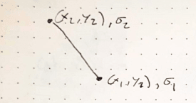
From Assumption 1 and 2 lets look at an arbitrary line segment defined by two points having stress,1 at point 1 and stress,2 at point 2:
Capture_uw2avw.png


Being an arbitrary line we now need some mathematically functions that define the line so that we actually have something to integrate, lets define the line using parametric equations in a time domain of 0 <= t <= 1:
x(t) = x,1 + t (x,2-x,1) - test: t=0, x(0)=x,1 and t=1, x(1)=x,1+ x,2 -x,1 = x,2
y(t) = y,1 + t (y,2-y,1)
sigma(t) = sigma,1 + t (sigma,2 - sigma,1) <--- Assumption 1: Stress is Linear

Now we have some math functions to have some fun with. Lets look at Green's Theorem:
Capture_rwwwvv.png


Assumption 3:We are going to rotate the cross section/plate so that the stress always only varies in the Y direction.

using Assumption 3, Force = Stress * area => Stress = F(x,y) => F(x,y) * area, but now stress only varies in Y so F(x,y) now becomes F(y)and because we are now looking at an Arbitrary line F(y) = stress = sigma(t):

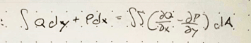
Integral Q dy + Integral P dx = dbl integral (dQ/dx - dP/dy) dA = dbl Integral F(y) dA = dbl Integral sigma(t) dA, note the dQ/dx and dP/dy are partial derivatives

since our function relies on Y lets try to find functions Q and P so that one of them drops out when we look at the partial derivatives:
Try:
Q = sigma(t)*x --> dQ/dx = sigma(t)
P = 0 --> dP/dy = 0

dQ/dx - dP/dy = sigma(t), which matches above so we can move forward now.

so now we have integral sigma(t) x dy + integral 0 dx, well integral of 0 is 0 so that piece drops off:
Integral sigma(t) x dy
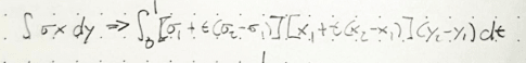
We need to now substitute it to get everything in terms of variable t
remember from above: x(t) = x,1 + t(x,2-x,1)
for dy we know y(t)=y,1+t(y,2-y,1) so then for a small change in y we need a small change in t, dt:
dy/dt = (y,2-y,1) or dy = (y,2-y,1) dt
and substituting everything from above in we get:

Integral (sigma,1+t(sigma,2-sigma,1)) * (x,1+t(x,2-x,1)) * (y,2-y,1) dt

The bounds of this integral are now the time domain 0 to 1
Capture_rmvugd.png


You can use various tools to solve this integral symbolically, I've been using Maxima: Link

So all of that gets us to a formula for P for an arbitrary line segment.

Formulas for Mx and My are found in a similar way:
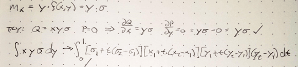
Knowing that Mx = Force * some y distance and force = stress * area
then Mx = dbl integral y * F(x,y) dA = dbl integral y*F(y) dA = dbl integral y*sigma(t) dA
Green's Theorem substitution:
Q = x y sigma(t) --> dQ/dx = y sigma(t)
P = 0 --> dP/dy = 0
Capture_dnnhna.png


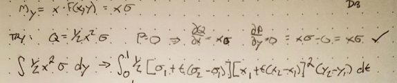
Knowing that My = Force * some distance x and Force = stress * area
then My = dbl integral x * F(x,y) dA = dbl integral x*F(y) dA = dbl integral x*sigma(t) dA
Green's Theorem substitution:
Q = 1/2 x^2 sigma(t) --> dQ/dx = x sigma(t)
P = 0 --> dP/dy = 0
Capture_dvs2pn.png


Solving all of the above integrals will give you general formulas for P,Mx,My of an arbitrary line segment.

You'll notice though that point 1 of the segment needs to have a stress value, what happens if the stress region is only partly on an edge segment?
In this instance you need to break up the segment to fit within the integration bounds and create a new segment where the first point lies at the exact point of 0 stress.

Also of that work above was just for a line segment to get the total P, Mx, and My you sum all of the segment components for the entire stress boundary. one thing you may notice is that each integral has a (y,2-y,1) term so if Y is constant across a segment it's contribution to P, Mx and My is 0 so if programming this you could include a check and skip those segments to help improve computation time.


Edit:
So one thing which may not be immediately apparent is, what happens if your stress function F(x,y)=1?

Well the P integral becomes -> dbl integral 1 dA, which the volume of an object with unit height is equal to the Area of that object

From mechanics of materials the first moment of area or elastic section modulus is:
integral x dA or integral y dA, which should look pretty similar to the formulas we just derived above for My and Mx

Again from Mechanics of materials the second moment of area of Moment of Inertia is:
integral x^2 dA or integral y^2 dA, following the procedure above we could come up with Q and P functions for these and use Green's Theorem again to get an integral for an arbitrary line section.

So that is a long winded way to say if the stress function, F(x,y), is equal to 1, then the results of the integrals are just the geometric section properties of the shape you've defined by line segments.

For area you may be familiar with the "Shoelace" formula, our formula for P above with an F(x,y)=1 is actually the derivation for the "Shoelace" formula.Link


My Personal Open Source Structural Applications:

Open Source Structural GitHub Group:
 
Thanks celt...

Rather than think climate change and the corona virus as science, think of it as the wrath of God. Feel any better?

-Dik
 
yakpol... still using your excel sheet for continuous beams... almost been a couple of decades. It only runs on my Win7 machine, but works great. I've tried to get it to work with Libraoffice calc to no avail...

Rather than think climate change and the corona virus as science, think of it as the wrath of God. Feel any better?

-Dik
 
Celt, judging from the subject, this project is for entertainment rather than for productivity. Working with live formulas using Smath or MathCad one can come up with a truly elegant solution, working on which would be way more satisfying than worrying about correct cell references in unruly Excel.
Nowadays I try to use excel only for GUI and databases (including that continuous beam that dik mentioned). Anything complex is better done in MathCad or VBA.
Yakpol
 
Status
Not open for further replies.
Back
Top