Eng-Tips is the largest engineering community on the Internet

Intelligent Work Forums for Engineering Professionals

  • Congratulations waross on being selected by the Tek-Tips community for having the most helpful posts in the forums last week. Way to Go!

Excessive Pivot ratios in shell mesh 2

Status
Not open for further replies.

ahildershavn

Mechanical
Nov 27, 2015
15
0
0
NO
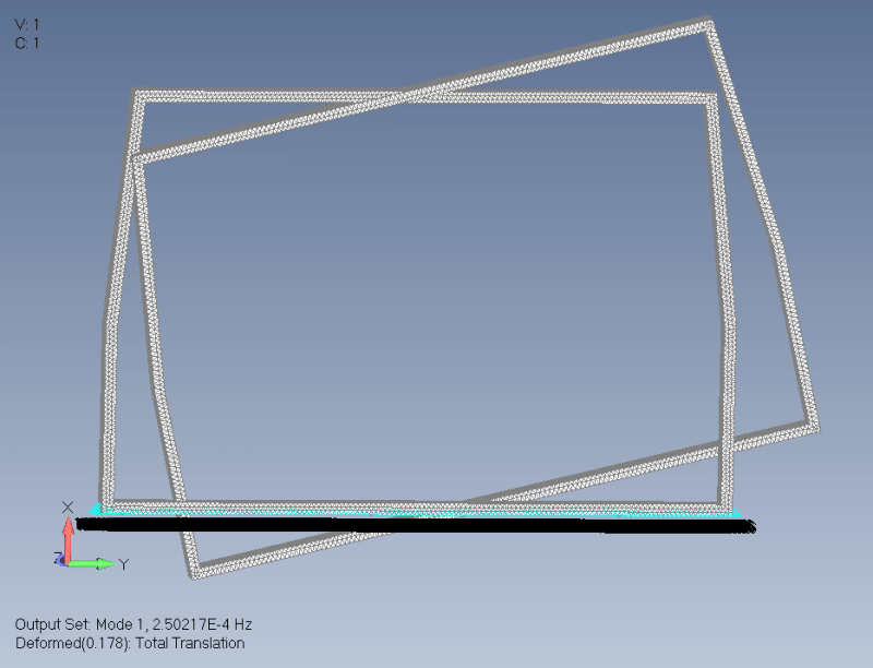
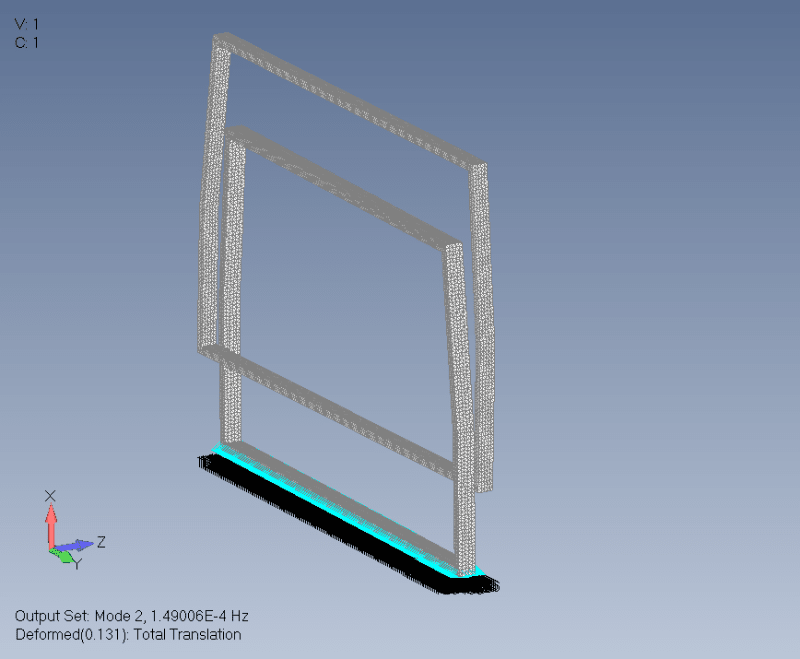
Hello, I have this simulation attached.
It is a frame and it is shell meshed. However I am struggling to run a simulation on it because I always get an excessive pivot ratios error. I have tried running Bailout -1 but to no help. Could not figure out where the error is.

Can anyone help me here? I was unable to post in the siemens forum because there is something wrong with the homepage there.

-Andreas-
 
 https://files.engineering.com/getfile.aspx?folder=a58551ba-8e08-4096-9770-a17b4433cdaa&file=model_merged.zip
Replies continue below

Recommended for you

Siemens forum in process of migration to new engine, check announcements.
Look like your model is poorly constrained, run sol 103 (modal) and check first near zero modes. Fine constraint model should not have them. You can check deformed shapes to see what parts of model not connected to whole structure.
 
Well, I have tried sol 103, I have tried adding a variety of different constraints, I have tried different element types. I have tried BAILOUT -1, INREL etc. etc.

To me it seems like a bug in the solver/software. Seems like some elements have no stiffness at all, but I have checked material and thickness. No issue there.

I have even tried to rebuild the cad from scratch.

Any help would be appreciated.
 
 https://files.engineering.com/getfile.aspx?folder=a5317236-65fe-43b5-a37e-db1812498b56&file=280819test.zip
Can you attach solver input file (.dat file that created in project directory after solver run). Some users, like me use Femam instead of NX.
ahildershavn said:
To me it seems like a bug in the solver/software. Seems like some elements have no stiffness at all, but I have checked material and thickness. No issue there.
I`m 99% sure that bug is not in solver/software but in ahildershavn. Look like you make some error when create model and can nod find it. Karachun bet on disconnected mesh/duplicate nodes
 
I think the elements are plane strain elements (MID2 is set to -1 which is plane strain) - in PSHELL MID2 set it to 1 for MAT1 and it will be a mem.+/bending shell element- also the inner and outer tubes/sections are not connected with each other - as suggested run a modal analysis and you will see that (since there is a restrain on the outer section only) the inner part/tube is "flying" away. If this is a RHS/SHS you only need the one of the two tube sections (either outer or inner, but not both) Hope this helps.
 
You have Two plate parts. Outer part is constrained but inner part is neither constrained nor connected to outer part. So, it not constrained and can move free. In addition, plane strain elements don’t have stiffness in all directions (I delete inner part, run normal modes and have one rigid mode) so I recommend to use general plate elements, unless you are know what you are doing.
1_mgaiv4.png

2_s7e2um.png

3_rsyrtm.png
 
Thank you.

I was unaware that I had created two 2D-mesh frames.
Attached here is the geometry I really wanted to simulate. Also, I have now managed to solve it using Erik Panos tips for PSHELL1.

I only have few question left then, what happens in PSHELL1 when Material 4 is left blank? And is it correct of me to define material for both MID2(Material 2) and MID3 (Material 3)?
Untitled_edakxs.png


Great forum!
 
I think that is OK - MAT4 is for bending-membrane coupling which can occur if material prop. say are are not symmetric with respect to the midsurface of the shell.

Here is something from the documentation:
The MID4 field should be left blank if the material properties are symmetric with respect to the mid-surface of the shell. If the element centerline is offset from the plane of the grid points but the material properties are symmetric, the preferred method for modeling the offset is by use of the ZOFFS field on the connection entry. Although the MID4 field may be used for this purpose, it may produce ill-conditioned stiffness matrices (negative terms on factor diagonal) if done incorrectly.

If you are unsure just do a simple test model and compare hand calcs to your FEA (say pressure load on a square plate - simply supported)
 
Status
Not open for further replies.
Back
Top