Continue to Site

Eng-Tips is the largest engineering community on the Internet

Intelligent Work Forums for Engineering Professionals

  • Congratulations KootK on being selected by the Eng-Tips community for having the most helpful posts in the forums last week. Way to Go!

Experimental Modal Analysis

Status
Not open for further replies.

E2015

Civil/Environmental
Apr 20, 2015
22
Hi everybody,
Can anyone comment my work, since I'm new in this are? I'm trying to perform SIMO analysis in MAtlab.

I have done an analysis of Euler-Bernouli beam subjected to square force in the middle of the beam in Matlab. Using Wilson's Theta numerical integration method I have calculated the beam response, e.g. accelerations, velocities and displacements for the applied excitation. Time step for calculation is 0.002sec. Load magnitude is 25kN and durations is 0.5 sec. The time sampling interval is 5 sec. The force is applied in the middle of the beam, what coincides with the 6th node.

Now I want to obtain point FRF. I know that FRF is the ratio of the beam response to applied loading, i.e. displacements to square force in frequency domain, but here are some unclarities how to obtain this in Matlab.

I'm not sure what should be the sampling frequency. Is it 1 over time step 0.002 for which I've calculated the beam response, or is it 1 over the time sampling interval of 5sec? I've used the time sampling interval, but I don't know is it correct.

Then, I have performed the fft of the displacements for the node where the load is acting and only for translational DOF. Fft of the force I've also done. The absolute values of both are calculated.
Here is the code which I have used for obtain the FRF's:

%% Calculation of beam response in the middle and applied force in frequency domain

Fs = 1/T; %Sampling frequency in Hertz
timeinterval = time; %time = (0:dt:T)

% FFT of displacement at 6th node for translational DOF and force vector
DISP = fft(displace(11,:));
P = fft(Pn);

% Calculating absolute values of displacements and force in frequency
% domain
DISPabs = abs(DISP);
Pabs = abs(P);

displength = length(DISPabs)/2;

Displacement = DISPabs(1:displength);
Force = Pabs(1:displength);

% Calculating FRFs and plotting
FRF66 = Displacement./Force;
Nyquist = Fs/2;
frequency = linspace(0,Nyquist,displength);

figure
semilogy(frequency,FRF66);
grid on
title ('FRF 66')
xlabel('Frequency (Hz)')
ylabel('Amplitude (dB)')

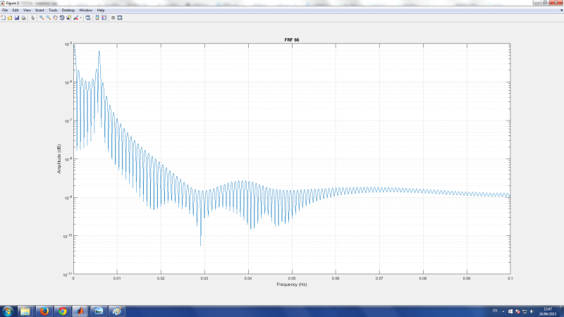
I have also attached the picture with the results of the beam response,
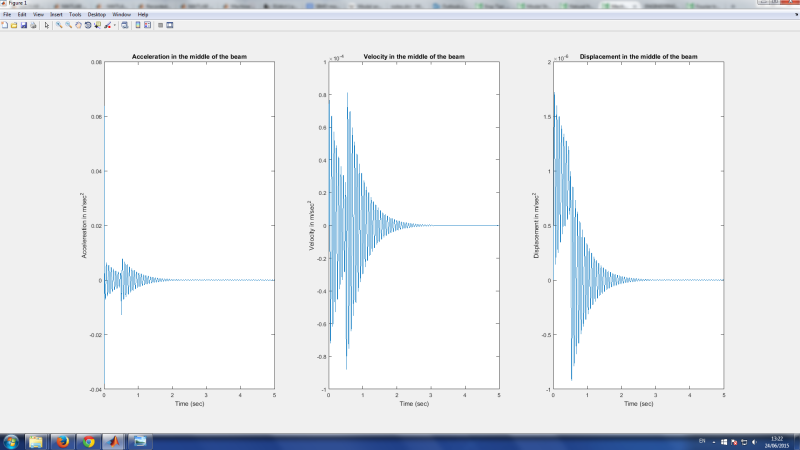
Beam_response_qdpgx1.png

and picture of the FRF at node 6
FRF_66_xkxtcj.png


Would it be reasonable to calculate the power spectral density with periodogram or welch method instead of doing just fft?

Can anybody comment my work, because I don't know is this exact, am I going in the right way?

Please help!
 
Replies continue below

Recommended for you

You seem to be in over your head, although I'd be the first to agree that Matlab offers slightly too many options for TFs

"square force " - what is that?

"The time sampling interval is 5 sec" Bet it isn't, sample interval =1 /sampling frequeny, i think yoiu are talking about your frame length in seconds, hence you should have a resuolution of 0.2 seconds and a nyquist frequency of 1/.002/2=250 Hz

Do you understand Welch? If you do, great, use it.

If not then you are trusting somebody else's black box. Why not take the FT of the input signal and the output signal, and look at the complex ratio of them? That surely is the essence of a transfer function (even if computationally it is inefficient compared with welch), it can be checked for reasonableness, done by hand, and so on.


Cheers

Greg Locock


New here? Try reading these, they might help FAQ731-376
 
Hi GregLocock,
Thank you for your answer.
I'm at a learning stage of EMA, that's why I'm struggling that much.
"square force" in my example is force of 25N magnitude and total duration of 0,5 sec. Since I don't have a real recordings from an impact, I have used force of a square shape just for learning purposes.

I have misunderstood the terms sampling interval and my frame length, but now everything is clear.

I'll try with Welch and see what I get. Would it be reasonable to use the exponential window here? I have seen from the literature that this type of window is used for data from transient signals. What about other types for PSD estimation in Matlab, as pburg, pyulear or peig? Which of them are most used when dealing with data of transient signals of short duration?

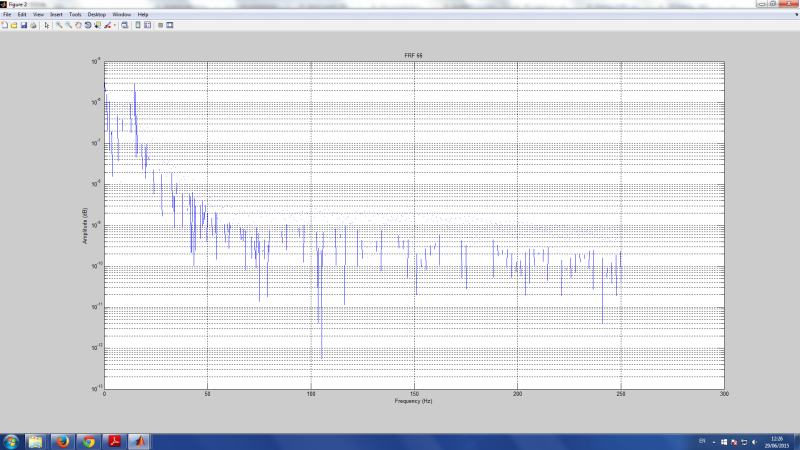
I have now the complex ratio of the input and output
Complex_ratio_bc7d6o.png
but I don't know what this should tell me.

Maybe I ask stupid questions, sorry, I just want to understand the point.
Cheers!
 
In a linear system the shape of the force signal in the time domain is unimportant, hence using a square' signal is just a choice, and in fact a bad one, as it does not include every frequency. usually one would use a Dirac pulse, a very short half sinewave pulse, a sine sweep, or some sort of white noise signal.

You desperately need to read a coherent introduction to modal, Ewins is the obvious candidate.


Cheers

Greg Locock


New here? Try reading these, they might help FAQ731-376
 
For SIMO analysis, it's not necessary to start with a beam structure, you can simply start with one oscillator : Mass-Spring-Damper.
The FRF is very simple FRF = 1/(Mass(omega0²-omega²)+j*Damper)
Use a Bode diagram for vizualization.

Then, you can add more oscillators.

Beam is a continuous system, i.e. there are an infinite number of oscillators!

From the plot, you can try to retrieve the damper value using the -3db bandpass method, for example...


Somewhat true, although the -3 dB method is notoriously unhelpful for real systems, but basically off topic for the OP.

Cheers

Greg Locock


New here? Try reading these, they might help FAQ731-376
 
M. Locock, you have to know that I will NEVER agree with you even when you're absolutely right :).

The -3dB method is very efficient and helful when the system can be analysed using SIMO technique.
SIMO implies that modes are well separated.
If you can isolate one mode from all the others, then -3db method is a very good tool for estmating damping.

The problem with E2015 is that I don't understand the relationship between his goal (to do SIMO analysis) and the choice of his model.

I think that you should ask to yourself :

What is the objective ? To do SIMO analysis for ...
What is the best structure for this ? Discrete systems or continuous systems ?
If continuous system is choosen, what is the best model ?
What should be the parameters for this model ? Structure (Beam, plate, others), Boundary conditions, Excitation...
What is the best method for solving? Analytical ou numerical method?

 
There are two situations where MIMO have to be used instead of SIMO :

1. One single excitation can't inject enough energy in the whole structure.

2. Modes are coupled (they are not well separated, several modes exist at the same frequency)

In the second case, you can interpret this from the point of view of the information theory : You don't have enough information about the dynamical behavior of the structure. But by exciting the structure in differents points, you get more information in view to determine the modal model of the structure.

Please don't try to be smarter than me ...
 
Your SIMO comment was nonsense, for many years we did SIMO on full vehicles over the frequency range 1-48 Hz. A vehicle has approximately 30-40 significant modes in that range, which had to be fitted by hand, quite often, rather than just a MDOF curve fit. Yes, sure these days we'd probably do a MIMO on a full vehicle, but that was not really a practical option, then, although at the time we did see demonstrations of MIMO on the space shuttle by the software developers so we knew what was coming.

You might be wondering how we validated the extracted mode shapes, frequencies and damping, quite simply we resynthesised the original FRFs, a process which is perhaps the forerunner of some of the more modern fitting techniques. Other validation techniques included performing a modal from a second driving point and checking reciprocity, and typically we'd start a project by doing several mini surveys from different driving points and deciding which driving point gave the best quality data and modal excitation.


Cheers

Greg Locock


New here? Try reading these, they might help FAQ731-376
 
Thank you GregLocock and Amanuensis for your comments and suggestions.
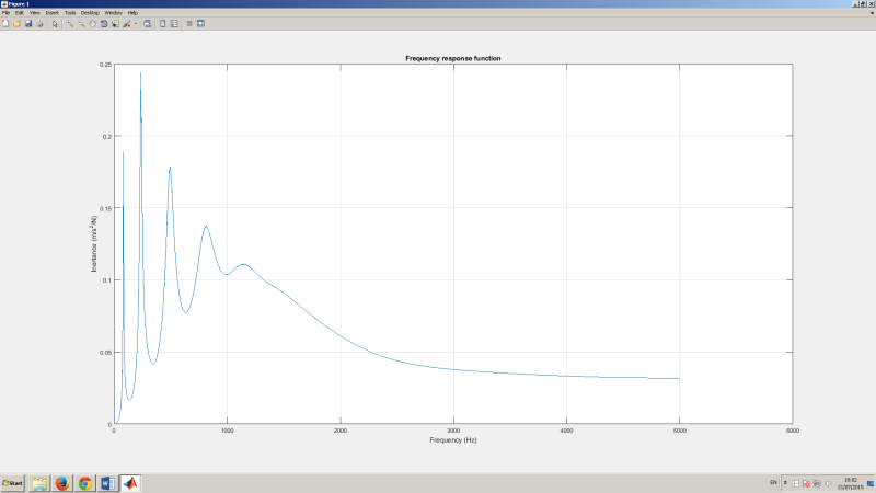
I have done the roving hammer method with eight impacts. Now my results show some sense what means that peaks of the FRF are visible and they correspond to values of natural frequencies. The values of first two peaks are almost identical to the first natural frequencies and they are tapered the most, the third peak value is also almost the same as the third natural frequency but the peak isn't that much tapered.
How can I make other peaks visible on my FRF curve? Should I apply greater force? Anny suggestions on this topic.

I have attached the final FRF curve which I obtained with calculating the ratio of auto power spectrum of output and cross power spectrum of the input and output using cpsd function in MATLAB with hanning window length equal to number of samples.
FRF_ltjdzv.png


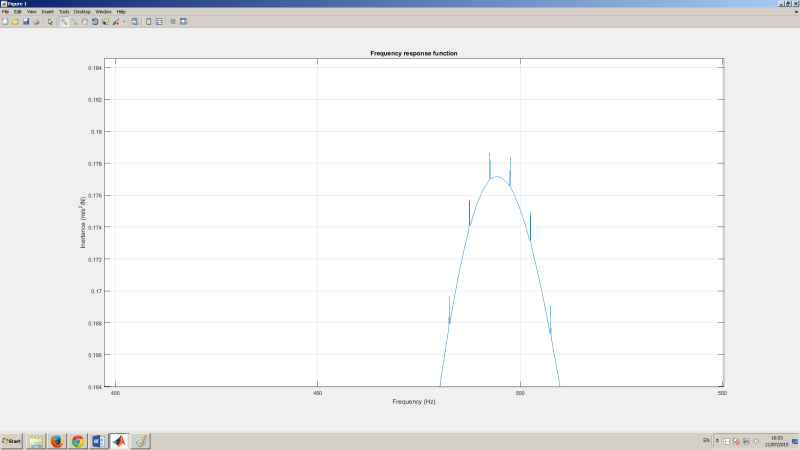
Also on my plot there are some anomalies. I have zoomed this on the following picture. Is this happening because of the type of window I used? Any suggestions how could I smooth the curve.
Anomalies_cnfa4o.png


Comments and suggestions are welcome.
Many thanks!

Emina B.
 
One word about "tapered peak".

As you can see, tapering decreases with peak number.
It means that the damping is certainly viscous or hysteretic.

You can try to verify for each peak if (Delta f)/f = Constant ( where f is the frequency of the peak and Delta f is the passband located at Ymax/sqrt(2) ).

 
Status
Not open for further replies.

Part and Inventory Search

Sponsor