Continue to Site

Eng-Tips is the largest engineering community on the Internet

Intelligent Work Forums for Engineering Professionals

  • Congratulations SSS148 on being selected by the Eng-Tips community for having the most helpful posts in the forums last week. Way to Go!

Eye bolt in thin plate - what is minimum thickness?

Status
Not open for further replies.

Gymnast

Electrical
Mar 22, 2008
22
Dear Sirs

Please see attached drawing.

Eye_bolt_in_thin_plate_bobldj.jpg


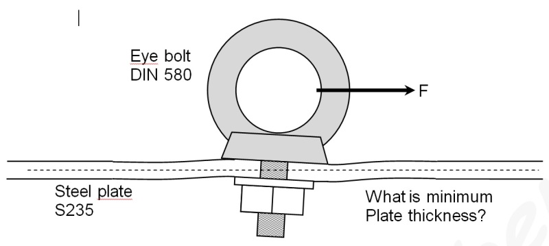
I am going to use a M12 eye bolt DIN 580. And the force is applied parallel to the base plate. You can find specifications on the eye bolts here:

DIN 580 Eye bolt spec

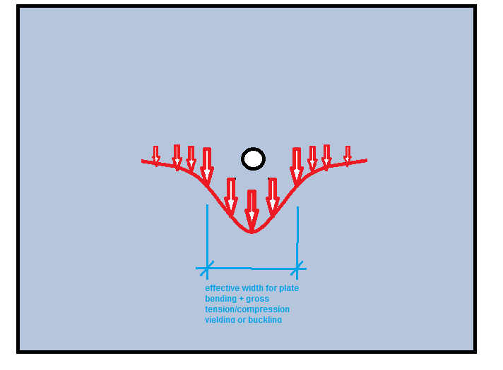
The WLL for the eye bolt is 1700 N, and normally the breaking strength is 5 times higher eg. 8500 N. How thick should the plate be to support the eye bolt? I expect the force to be applied 30 mm above the plate surface. I suspect that the moment applied to the plate is the critical factor.

I should love to know the solution for this specific question and perhaps in more general terms. I suspect, that limits to the moment on a bolt in a plate is a quite common question. However I am no structural engineer, and I have not been able to find the answer here or by google.

Thank you in advance for your help.
 
Replies continue below

Recommended for you

Tough problem. You may want to check that the eye bolt is rated to be loaded in that direction. Somehow I recall it has to be no less than 45 deg. form horizontal.
 
XR250 - I think the DIN 580 standard specifies a maximum of 45 deg. load. However most manufacturers specify half load to the side eg. 90 deg. Please look at the link in my post.
 
Best solved by FEA, but there are approximations for moments on plates in Rourk's formulas. Shear at the influence perimeter might control for tear out; however, you can get a lot of distortion before that occurs.
 
Be very careful! There is a lot going on here for a non-structural person. I hope this does not involve human life-safety - if so, you should have a structural/mechanical engineer help you out. One tough thing for your calc is determining the effective width of the plate (transverse to load direction) that can be used to resist the load. The effective width is a function of poisson's ratio and also the thickness of the plate. In gusset plates, the "Whitmore Section" is a common way to limit the effective width to extents of the peak stress distribution.


Search for "whitmore" in the forums for more posts.

If the plate span is long, you will need to consider buckling from the compression component of the load. Regardless, you need to consider combined bending and axial stresses (P/A + M/Z) over that effective width. Further, bolt bearing will need to be considered. It looks like edge distance is not an issue??

sketch_wfoybf.png

Good luck.

"It is imperative Cunth doesn't get his hands on those codes."
 
Ron - you beat me while I was composing!

"It is imperative Cunth doesn't get his hands on those codes."
 
That orientation for lifting is strictly forbidden in the catalogues on lifting I've seen.

“Do not worry about your problems with mathematics, I assure you mine are far greater.” Albert Einstein
 
One time loading, twice a week, or supporting a piece of running equipment?

Is permanent bending considered "failure?"

Is visible temporary distortion considered "failure" ?
 
Thanks for the replies.

I hoped for an easy solution, but apparently this question is more complicated than I anticipated. So I suppose I need a qualified structural engineer for this. I have tried to look for Whitmore, but It did not help me. Please note, that I am not a structural engineer, so I normally only make calculations of simple structural problems.

Tmoose - The loads are dynamic. The maximum dynamic loads is 1250 N, and this might be reached 5 times a week. We are going to make a controlled check once a year up to 2800 N. Typically loads up to 500 N will be applied 200 times a week. And most of the time there is no load. Permanent bending up to 5 degrees should be all right. The loads are mostly from one direction only within 15 deg. I am told, that normal safety factors for this kind of use is 5 times to the limit of elastic deformation.
 
Eye bolts can be loaded as show in the sketch by the OP. On this site, the tables show allowable loads in the vertical direction, 45d and 90d from the vertical.

what's critical in the sideway loading of eyebolts are the need for shoulders incorporated in the eyebolts and the pulls be in line with the bolt heads as shown in the sketch.

The OP should have stated the thickness of the plates, number of eye bolts used on a plate, spacing configuration between eye bolts.
 
I would be rearranging the support structure so you had it being pulled at zero degrees. Firstly you would get more capacity out of the eye which isn't a bad thing, secondly a tension load on a plate with a bolt is more readily assessed and plate yield lines can be controlled via suitable stiffeners etc to control leverage/lever arms etc.

You then just provide sufficient structural members to support the given loading back to where ever you are supporting the loads to (I.e. Get a structural engineer involved).

I wouldn't be loading the eyes past the 45 degree case as tempting as it is, the standard has this recommendation for a reason and you cannot infer the same capacity past the 45 degree mark.
 
Agent 666, I would agree with you at the 45d case, howerver such practice is more exercised in rigging work. I don't believe that this is the case with the OP.
 
I have seen websites from several agents selling eye bolts and eye nuts, with different specification on side load. The geometry can vary too. But quite many agents (and perhaps manufacturers) do specify 50% load at 90 deg. All just say no load to the side parallel to the center line of the eye. Example of suppliers with 50% load at 90 deg. :

Elesa-Ganter
Mec-Wolf
Wixroid
Reyher p75 and p148

I cannot go into all details of the application, but in this case it is practical to make use of side load, and 50% load limit is not that bad.

Ron, thanks for the reference to Roark's formulas. Am correct to suggest the formula on page 494, 21b here? Sorry, I cannot link to Roark's formulas because the link has an apostrophe. But google is your friend.
 
Put a couple of vertical stiffeners under the plate and use a thinner plate. It will be cheaper than a thicker plate.


Mike McCann, PE, SE (WA)


That design just looks like a recipe for disaster. Your point loading on the front face of the eyebolt "collar" will be huge. With a repetitive transient load you're going to fatigue that part out very quickly.

It would seem to me that you need to spread that load out a lot more - something like the systems below. The second one is mickey mouse, but illustrates the idea I'm getting at.


Remember - More details = better answers
Also: If you get a response it's polite to respond to it.
 
Status
Not open for further replies.

Part and Inventory Search

Sponsor