Eng-Tips is the largest engineering community on the Internet

Intelligent Work Forums for Engineering Professionals

  • Congratulations waross on being selected by the Tek-Tips community for having the most helpful posts in the forums last week. Way to Go!

F1 engine, deck ridges ? 4

Status
Not open for further replies.

Rat5

Agricultural
Aug 6, 2016
29
0
0
FR
What are those small deck ridges ? ( bmw f1 engine 1500cc 1200hp)
20200805_041444_zomzdc.jpg
 
Replies continue below

Recommended for you

BigClive.
The block is a non-sleeve cast iron design used in BMW road car engines (M12). (Observations and opinions start here.) When modified for F1 any sleeves added would have to be "dry". (I don't think this was done). A wet sleeve system needs the block designed that way from the ground up so this was not a wet sleeve system.

The counterbored cylinder can only be to accommodate a metal o-ring - the M12 gasket in the above link would not work. The grooves clearly run from said o-ring to atmosphere. The purpose can be deduced and coincides with the information that was disclosed 38 years ago.

For those not familiar with o-ring decks. The "o-ring" is the only seal around the bore ie it extends from block to head face with no gasket material. The head gasket covers the remaining head surface. The o-ring is usually copper with flat sealing faces top and bottom.

Alternatively it can be a hard material eg stainless steel or inconel with a knife edge on top to "bite" into the cylinder head. This design will accommodate more dimensional variation eg under high thermal gradients. (0:23 in the video shows a flat cylinder head face so the o-rings were also flat).


je suis charlie
 
None of this was worth disagreeing over but some things to be straightened out. The general information about the engine may be the most ambiguous information about an engine that's been. Starting with this, the BMW M12 engine never raced in F1.

The BMW M12 engine began being used in 1962 as an F2 engine. This engine never made anywhere near the hp numbers stated here. It never raced in F1 until 82. Starting in 82 the F1 engine specifically used old used blocks. The blocks were re-machined, usually with sleeves and with the turbos the completed engine was capable of about 1,100 hp. It qualified at about 850 and raced at about 650 so it could last the race. This engine was actually rebadged as the BMW M12/13. USF&G bought the engine program 86 and more changes to the engine came. This engine was rebadged again as the BMW M12/13/1 and then re-badged as the Megatron. BMW may not have made a dry deck aluminum block but others definitely did with some stated to exceed 2,000 hp. The engine was dated and gone by 89 when F1 banned turbos. The Ford Cosworth DFV's was a much more powerful naturally aspirated engine.

The original M12's were still in use for F2 and Touring Racing until the early 90's. The original M12's were about a 350 hp engine and was a derivative of the M10 which was based on the design of a straight 4 motorcycle engine.

An interesting trivia fact about the M12/13 engines and about using the used blocks. It's where the whizzing on a hot block for strength myth came from.

The engine's been gone for 30 years and was never a common engine in the US so information on the engine isn't easy to track down although there is limited information available, mostly in books by former machinist's and mechanic's from the racing teams. Some are available for viewing at The Henry Ford's archive but I don't believe any are in English.

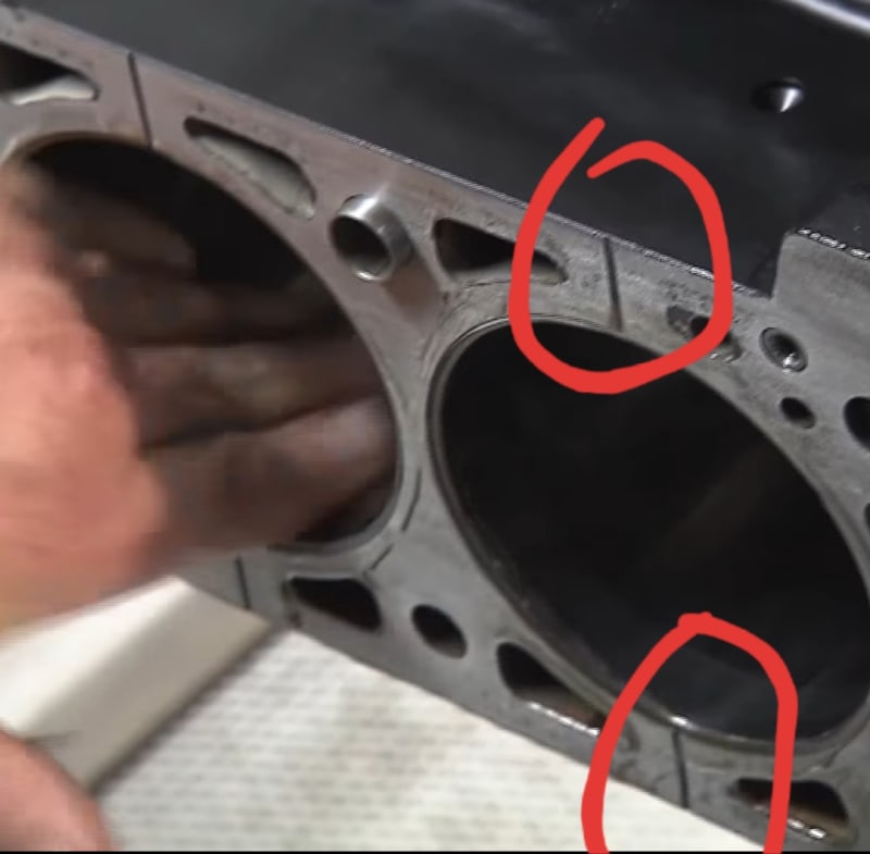
Did the original M12 engines have the groove? I don't know for sure. But I've never seen or come across it before the re-machined M12/13 engines which again began in 82 when the engine entered F1 racing. The reason for it, as I've come across was heat differential between the sleeve and block when the engine was operating at temperature. The sleeves didn't use any other method to locate and hold the sleeve such as flat on the flange.

EDIT: More trivia, in 87 F1 limited turbo boost to 4 bars and in 88 it was limited to 2.5 bars. That equates to 58 and 36 PSI of boost.
 
My mistake - I meant M10. The M10 was a road car engine and well-used (seasoned) blocks were repurposed for the Megatron turbocharged Formula 1 engine. This was the only variant of M10/M12 engine to have the relief grooves added to the deck.

The relief grooves were not present on the original Formula 1 engine either. This was a revision to the design introduced after instances where head gasket (bore seal) failure led to dnf's after the coolant was ejected by combustion gases blowing across the deck and into the water jacket. The F1 turbo was probably also the only variant to use "o-ring" bore sealing.

je suis charlie
 
grunt,

I'm done with what the engine is or isn't. But, I did find this interesting about one of your links, which by the way I engine.

The You Tube video link was titled, "BMW F1 Car BT52 1,280 hp Engine Assembly". The BT52 was not a BMW F1 car. The BT52 was a Brabham F1 car with "BT52" signifying their sequential car number method. It used the BMW engine but wasn't a BMW car. Like I said, if this engine isn't the most ambiguous engine when it comes to information about it, it's got to be close to it. lol
 
I don't know where you're getting your information from, but... it's really not that complicated.

These engines are not a mystery. Parts and complete engines, while expensive, are available today, and BMW 2002 vintage racers are still raising hell with these powerplants in them all over the US and europe. Shops like Metric Mechanic are still rebuilding and modifying them.

gruntguru said:
The counterbored cylinder can only be to accommodate a metal o-ring - the M12 gasket in the above link would not work.

That is an M12 gasket - it fits no other engine. (M12 head gaskets do not fit M10 heads). The o-rings are not separate; it's effectively an MLS gasket with a foil-wrapped rectangular section 0-ring integrated across the gasket; the cylinder seals (the foil-wrapped ring) are thicker than the conventional MLS sections used through the rest of the gasket.
 
My point was the M12 gasket you posted will not work on the BMW/Megatron F1 block which requires bore sealing rings separate to the gasket.

je suis charlie
 
Yes, once the engine gets much longer than 3 feet manufactures start using individual heads per cylinder to mitigate the problems associated with thermal expansion.

IMG_20200714_113059_zvpiku.jpg
 
Not many 3 footers in F1.

----------------------------------------

The Help for this program was created in Windows Help format, which depends on a feature that isn't included in this version of Windows.
 
The bore seals may be of the 'U' or 'C' shaped cross section copper rings. These have the opening towards the combustion chamber and are energized by combustion chamber pressure and sometimes an internal coil spring. There may also be a coil spring inside. Because gas pressure inside the ring forces the seal outward against block and head surfaces, you would not want pressure build up behind the seal. The small channel would insure that the pressure on the back side of the seal was vented to atmosphere.
 
I know this is a logical conclusion but I don't agree with it. If the pressure behind the seal was equal to the pressure inside the seal there would be no pressure differential to cause leakage. There is an application listed with the seals installed opposite to pressure to reduce the volume of process fluid in the seal cavity.

 
A "C" shaped bore seal would create significant issues due to the crevice volume added to the chamber perimeter. I haven't seen anything of that type used in this application.

je suis charlie
 
I have used the 'c' shaped cross section seals with internal springs as head gaskets. see page 21 of TugboatEng's reference. The volume was relatively small and emissions weren't an issue. First saw them mentioned for head gasket use in a book on diesels if memory serves.

Mercury Marine outboards have also used rubber 'O' rings as combustion seals on two strokes in the manner TugboatEng describes for the Yamaha. The cylinder spacing resulting from the transfer ports surrounding the bores provided enough deck area to space the groove relatively far away from the edge of the bore and there are no push rods or oil returns to claim the space around the top of the bores.

The equal pressure resulting in no leakage argument ignores the large cyclic variations in the four stroke combustion chamber pressure during operation. If high pressure accumulates behind the seal you could get movement, wear and fatigue.

 
All I have to say about those deck grooves is WOW. As well as everything else in both the posted photos of the grooves. So how long ago was this being done?
 
Status
Not open for further replies.
Back
Top