Eng-Tips is the largest engineering community on the Internet

Intelligent Work Forums for Engineering Professionals

Fabricated Steel Form Questions 2

Status
Not open for further replies.

UTvoler

Structural
Oct 7, 2010
49
0
6
US
Hello all you concrete form experts!
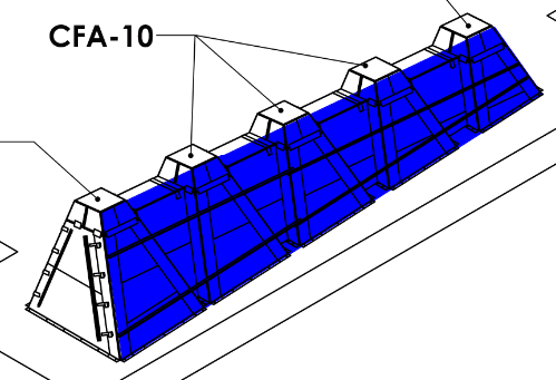
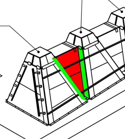
First form design here for a valued client, so I can't say no. The forms will be fabricated from sheet steel, to pour a ~ 43-ft long concrete mass varying from 6'-10" high to 3'-4". See attached sketch cross section.
A couple of rookie questions:
-I think I have to assume the lateral pressure from the concrete as normal to the form surfaces; so there will be fairly significant uplift due to the sloped forms? They are being erected on an existing slab, and will be fastened at the base with xxx anchors at xxx spacing.
-There will be kinda-sorta steel angle walers along the length, sloping as the form decreases in height. I'm told internal ties are not an option, so I'm left with bracing. If I'm pinned at the bottom slab connection, and the two sides of the form are connected with straps at the top can I possibly use walers along the height of the form at whatever interval is required? I'm thinking with the non-symmetrical angles on the two sides I will have a net force one way trying to push the form over?
-Any other words of wisdom to kick my design off on the right foot?

Thanks in advance!
 
 https://files.engineering.com/getfile.aspx?folder=74e8de92-54ec-4b7f-a69f-fb49fd7a9011&file=form.PNG
Replies continue below

Recommended for you

Keep your deflections small.

If you have no control over the pour rate, then design for full liquid pressure.

Get a copy of ACI 347R (Guide to Formwork for Concrete), as well as a copy of "Formwork for Concrete".

This is a tough scenario - the uplift is no joke. Free-body diagrams are your friend.

Please note that is a "v" (as in Violin) not a "y".
 
UTvoler said:
I'm thinking with the non-symmetrical angles on the two sides I will have a net force one way trying to push the form over?
That is an incorrect thought*, though I can see how initially you could conclude that.
**unless there is another form item in the 3rd dimension not shown.

Integrate the pressure around any horizontal slice and you will get zero. (assuming the form is a closure section) If this wasn't the case then a oddly shaped cup filled will water would accelerate sideways! Another way of looking at it is there nothing to produce a horizontal reaction apart from the form, so it must sum to zero.

Though as WinelandV pointed out uplift is not joke here. The ground reaction is the quite rude!
 
Yes uplift is certainly an issue here because of the slanting faces, and so many experienced people do not consider it until it happens. I had it happen to me in my younger days on one sided forms.

Agree with Human909 that sum of the horizontal pressures sum to zero, but integrating the upward component of the pressure leads to the upwards force and this has to be tied down.

 
Some thoughts -

a) not sure why "internal ties" not an option - these are almost always the most effective way to form concrete - and there are certainly ways to hide/minimize the tie holes (if architecturally concerned), or seal them, (if a water issue).
b) not sure if a single 43' long pour - or multiple - might influence answers
c) In the US, there are a number of manufactured systems out there that could be hugely beneficial - Symons Soldier system has many components (walers, connectors, etc.) that could be very beneficial (basically a structural Erector Set for formwork), and can be rented (and I think EFCO has a similar system). And there are multiple companies (including Symons, EFCO and others) that rent dedicated one-sided forming systems (basically A-frame, with large diagonal anchors at the base). Though anchoring these into an existing slab may not be feasible, as the loads add up quickly. FWIW, I am a former Symons employee (long-time ago).
d) Curious as to your role - are you working for the concrete subcontractor? Regardless, I would think you would want input from whoever will be installing and pouring concrete, as I would think that they would have thoughts, plus you want them on-board with whatever approach you go with.
e) And, to reiterate, uplift is definitely real.

Soldier_screenhot_fpmjb9.png
 
All, thanks for the thoughts and input.

@human909/civeng80: I like the cup analogy, but when I draw the FBD and run it in RISA with the pressures normal to the form I get an lateral instability so I must be missing something. If the two sides are not at the same angle (or height), the horizontal component of the pressures are not equal and so the model is not stable without a horizontal reaction or brace (see screen shot).

@jjl317:
a) "no ties" is coming from the concrete sub. This is a foundation for an amphitheater roof; so there is a ton of steel and rebar inside the concrete, and the face of the concrete is visible and "architectural" so they don't want to deal with trying to tie inside and finish the form holes. I haven't pushed back on this yet, but I may.
b) Not sure either, but I will likely have to assume a worse case scenario. I suspect it will be one continuous pour.
c) My initial sketch was a very simplified version of what is actually going on. There are "buttress" bump-outs along the length, and the form is very non-uniform along the length so I'm not sure a manufactured form system would be an option. But I'm certainly no expert.
d) I'm the "form contractor"'s engineer; they are a specialty steel fabricator that I do a bunch of work for but this is a one-off for them as well.
e) Indeed!
 
 https://files.engineering.com/getfile.aspx?folder=40546187-7542-4cdc-bf7b-1ee85f33064f&file=RISA.PNG
Looking at the desired shape, I dislike everything about this.

Yes, if they try to pour this all in one go, the high end will have more horizontal pressure than the low end. However, you should be able to contain those forces w/in the long sides of the forms - but that will be hard from a computation and detailing perspective..

I think you're better off designing each of the 4 sides to be stable in itself. Yes, this will require an external brace (or two, or 6). You'll still need to seal up the corners, but you won't be depending on those corners to keep this thing contained.

The saw-tooth effect in the long sides looks nice, but is going to be a nightmare for your formwork. I would design the long sides assuming it's all in one plane, and then have your fabricator weld trapezoidal steel boxes (w/internal stiffeners as req'd) directly to the plane.

Design plane for the long side:
Sample_Long_Side_wcdkhv.png


Possible internal plates to make the shape:
Sample_Internal_Bumpout_sdpoh0.png


Please note that is a "v" (as in Violin) not a "y".
 
@WinelandV, I don't disagree. But this a good client that I can't pick and choose projects with so I have to help them thru it.
What you see is what you get (as currently designed); the forms are 10ga sheet steel panels that are going to be fabricated with all the in's and outs, tapers, decreasing heights etc. The sides are two pieces of weldment, stitch welded together in the field and the ends are panels with toggle latches. I have to tell them what additional straps, bracing, walers, fasteners etc., are required to keep it all together.
 
Yikes - fair to say your original sketch simplified it a bit - haha

My first thought is that to try and VE into a simpler shape (though guessing not an option)

Second, similar to that I might consider using boxouts within the main formwork to achieve the insets - basically have full formwork similar to your original sketch, then attach supplemental boxouts to the face of the main formwork. That could simply the overall structural concerns.

Third, while I don't like them, and they would leave holes (but might be easier to handle in the rebar congestion), there are formwork ties to rebar out there - though does take considerable coordination, plus unless they are both perpendicular to the form surface, they will have a tendency to move laterally
ties_to_rebar_lpemm7.png


Finally, I am guessing they might need to use self-consolidating concrete to limit voids, which increases pour pressures even higher.

Hope this help, and good luck
 
Status
Not open for further replies.
Back
Top