Eng-Tips is the largest engineering community on the Internet

Intelligent Work Forums for Engineering Professionals

Failure analysis of a thin-walled tube

Status
Not open for further replies.

IngeniousQuest

Materials
Apr 16, 2024
12
0
0
GB
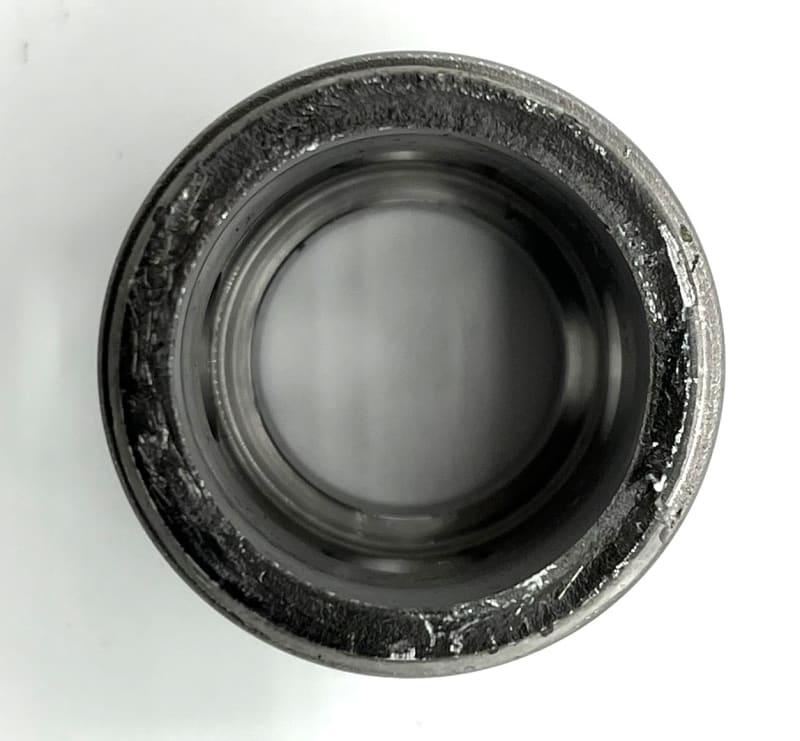
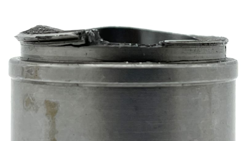
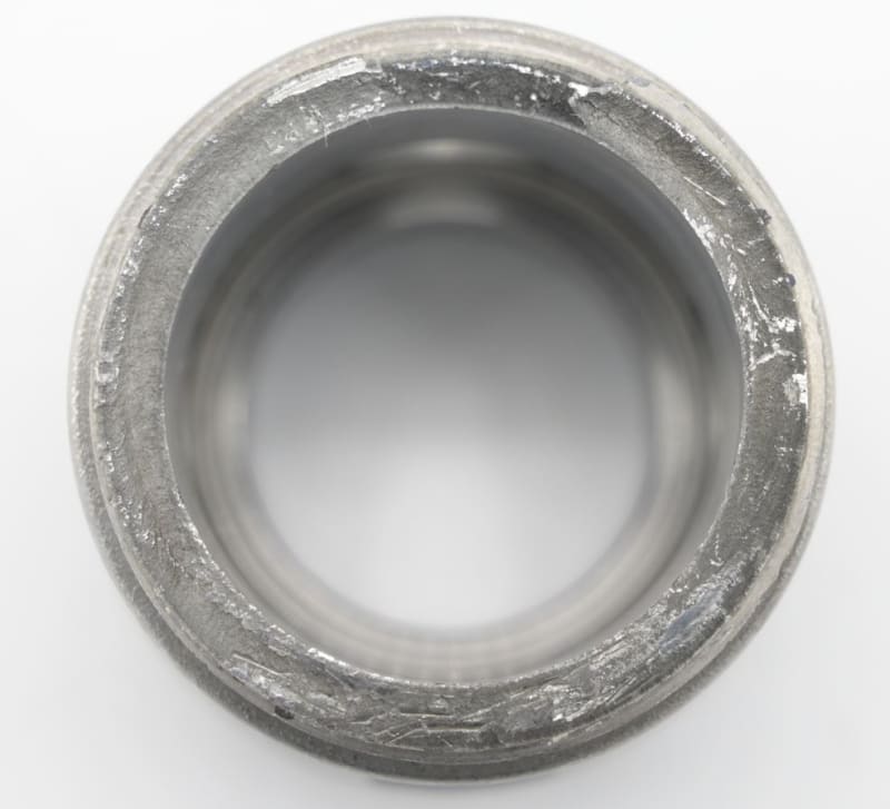
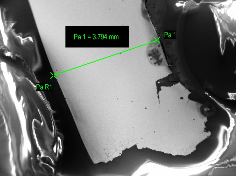
Could someone assist me in identifying the failure mode of the following thin-walled tube
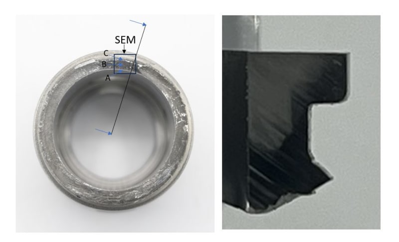
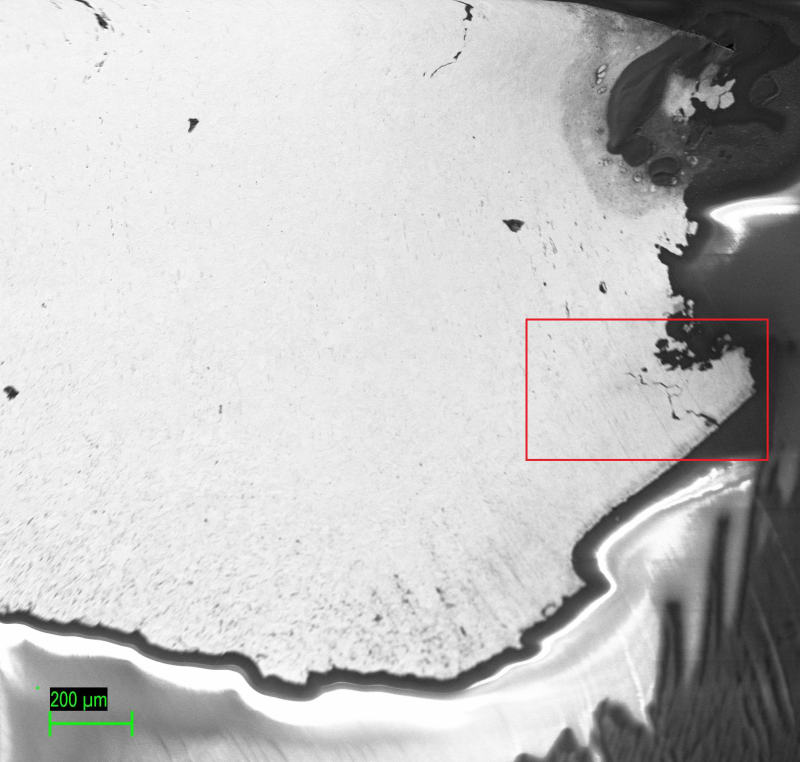
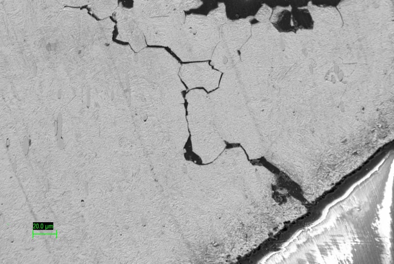
Microscopic images of locations A, B, and C (x1000) of the fracture surface as attached. I'm attempting to interpret the failure mode.

1. Thin-walled tube : [URL unfurl="true"]https://res.cloudinary.com/engineering-com/image/upload/v1713285821/tips/1_tbhwer.tiff[/url]
2. A : [URL unfurl="true"]https://res.cloudinary.com/engineering-com/image/upload/v1713285894/tips/A_btoelf.tiff[/url]
3. B : [URL unfurl="true"]https://res.cloudinary.com/engineering-com/image/upload/v1713285909/tips/B_n5mhoh.tiff[/url]
4. C : [URL unfurl="true"]https://res.cloudinary.com/engineering-com/image/upload/v1713285926/tips/C_yctap8.tiff[/url]
 
Replies continue below

Recommended for you

No macro?
No dimensions?
No material?
What was the loading?
I am not even looking until I have some information.

= = = = = = = = = = = = = = = = = = = =
P.E. Metallurgy, consulting work welcomed
 
Tube diameter? Pictures of the as-found tube in full size, from at least side and end view of both fracture faces?

edit to add: specification of material type (ASTM or material chemistry), location in service, type of service, adjacent welds?, exposure to corrosive materials, what type and concentration, temperature limits, prior machining and forming history. 60 ksi tensile test? No internal pressure?
 
As you might have guessed from the other comments, it is never a good idea to slap a few SEM photos on the internet with absolutely no context or information and then try to crowdsource a failure analysis. It is one thing if you are doing this for your own curiosity and no stakes are involved but you need to work with an experienced engineer if this is to answer a need for your company.

I will tell you that other techniques besides SEM are necessary to identify this failure mode. I would start with visual and macroscopic examinations and metallography but other techniques may also be advisable depending on the system and circumstances.
 
Hello mrfailure,

Tbh, I'm curious about how we can correlate microscopic features to different failure modes. This part has been on my desk for a while, so I lack enough information related to its service life and operational conditions. But, I'm confident it's related to a hydraulic system in some way. I did some microscopy and hardness testing out of curiosity and attempted to use them with Chapter 12 of the ASM Metals Handbook to identify the failure type. However, I'm facing difficulties in clearly interpreting the features of the microstructure at different locations as marked in A,B,C
 
In a hydraulic system you are likely to only see three failure modes.
1. External Corrosion
2. High Cycle fatigue
3. Single cycle or low cycle fatigue from 1 or a few high pressure cycles

= = = = = = = = = = = = = = = = = = = =
P.E. Metallurgy, consulting work welcomed
 
No evidence of corrosion is present, but the microstructure in region A resembles intergranular facets. Does this indicate fatigue failure, with crack initiation possibly attributed to impurity element segregation or hydrogen-induced embrittlement? Also, the absence of fatigue striations means a slow crack growth rate or less severe loading conditions.
 
Hello btrueblood , Top and sideview of the fracture face is as below ;

Top_thrj3i.jpg

SIDE_hiz5vo.jpg
 
First, I am usually in agreement with Ed but in this instance I think he way oversimplified the potential failure modes and may be shutting off thinking about other possible (albeit less likely) modes.

IQ: I think you inverted how you should approach a failure analysis. The first thing you should be doing is examining the component visually to see what might make sense for the failure and eliminate what does not. The pictures you provided help though you will need better lighting to show the fracture surface and you should also then clean it so you can better see features. We now know this is a full circumferential through-wall fracture. For this type of fracture you will get your most relevant data through the visual examination. That will tell you things such as fracture origin, final fracture region, and general fractographic features that can correspond to fracture mode.

I can only tell you what I think I see in the top photo; you should work on getting a photo that is better lit. Fracture looks to be OD initiated. The origin looks to me like it is at the 5:30 position. I base this on the fact there are a few ratchet marks at the OD and their angles indicate 5:30, where they are most perpendicular to the OD. The fact that you have ratchet marks suggests a failure mode of HCF (high-cycle fatigue), which typically is vibration induced. The ratchet marks form as a result of multiple cracks initiating which then band together. You cannot assume you will see striations, especially if the steel is ferritic rather than austenitic. Contact between the mating surfaces tends to destroy striations. Again, note I am just trying to interpret from a poorly lit photo, and others may interpret differently.

With regards to metallography: I would prepare a through-wall mount perpendicular to and through the origin. Among other features, you can determine if parallel cracks had also initiated (important if fatigue was thermally rather than vibrationally driven), whether cracking is branched as might be indicative of stress corrosion cracking, whether cracking is intergranular (HCF generally is transgranular), and whether you have an austenitic or ferritic steel. Etched microstructure, especially for ferritic steel can tell you about heat treatment, service degradation, and whether the surfaces were hardened and if so to what depth. Since you don't know the alloy, I would also place the as-polished surface in the SEM and run EDS in semiquantitative mode to help in identifying the alloy.


Your last photo changes the discussion.
This isn't a tube as in a plain straight section of tube.
This is a part with formed or machined features.
We need a lot more information now.
and you still didn't say what kind of SS it is.
If this is OD initiated, then it is most likely to be mechanically (perhaps vibration) induced and not related to the service pressure.
True hydraulic failures are always ID initiated because the stress are higher on the ID surface.
Cleaned and better lit macros.
And show us where on the macro the SEM shots are from.

= = = = = = = = = = = = = = = = = = = =
P.E. Metallurgy, consulting work welcomed
 
Well, at a sharp interface between a thin and a thicker tube has at least 2 different failure modes besides corrosion. In the case of mechanical fatigue, pipeline stresses will preferentially fail at such an interface.Typical examples are a pipe size reducer located next to a control valve and the valve fast-closes leading to water hammer and resulting massive pipeline stresses that concentrte at the reducer. Likewise, thermal stresses become enormous in the case of a very thin boiler tube welded to a much thicker header; The rate at which the mid-wall thickness varies by the square of the thickness, so a +/- 700 F fast change in fluid temperature duiring startup or shutdown can lead to a local metal temperature difference at the interface of as much as 450F, implying low cycle thermal fatigue.

"...when logic, and proportion, have fallen, sloppy dead..." Grace Slick
 
Not seeing the mating piece hampers our perspective. It is possible this failure really occurred at a weld that was then subsequently machined at the OD. This is another way a longitudinal would be used: You would be able to tell if it occurred at a weld and, if so, in the weld metal or in the heat affected zone.
 
Most metals will experience a limited fatigue life under a certain load/stress. The life could be shortened provided the load is excessive. A heating stress relief after manufacturing, could eliminate the residual mechanical and/or thermal stresses. A sharp bent corner should be avoided to reduce the stress concentration.

The bottom picture displays some tooling marks near the fracture surface where the breakage took place. The fracture appears torn along this is tooling mark, The presence of tooling mark could generate a detrimental stress raiser.
 
Hello guys, I now have a cleaned and improved ish macro image of the fracture surface, as well as a through-wall mount showing the fracture surface. Several intergranular cracks similar to the one in the last image were found but there were not branched (No stress corrosion cracking?? But can it we ). I did some EDX analysis too. Surprisingly, even though the parts seem very resistant to corrosion, I didn't find any Cr (So not a stainless steel???). But, I did find small amounts of Mn (<0.40%) and a noticeable amount of S (<0.6%) [prone to sulfur embrittlement due to MnS??], along with iron (Fe) and carbon (C). The hardness measured ~150 HV10.

Fracture_surface_gtbayj.jpg


CS_fracture_tdimwv.jpg


CS_c9hbyh.jpg


cs_200_gipz9f.jpg


Crack_o3zj4n.jpg
 
So you have no idea what the material really is?
What is the base metal, all Fe?

= = = = = = = = = = = = = = = = = = = =
P.E. Metallurgy, consulting work welcomed
 
A couple of comments:

-I like the unetched cross-sections, which shows the additional intergranular cracking. Now you should etch for microstructure. This will tell you (hopefully) if a weld is present and the relationship of the fracture to the weld and/or heat affected zone. You also will get confirmation of general microstructure. Given reported chemistry, a quick 2% nital etch should do it.

-Note that sulfur and molybdenum peaks overlap in EDS analysis. I doubt your steel would have measurable sulfur unless it is a free-machining resulfurized steel (pipe and tube are not usually made from that). You can try to confirm Mo by running your EDS at a higher energy (at least 20 kV but 30 kV is even better) to see if the higher energy Mo peaks are present.
 
Status
Not open for further replies.
Back
Top