Eng-Tips is the largest engineering community on the Internet

Intelligent Work Forums for Engineering Professionals

Fastener joint modeling using single RBE2 instead of CBUSH w/ "spider" RBE2

Status
Not open for further replies.

hootrpootr

Aerospace
Feb 28, 2020
27
0
0
US
Hello,

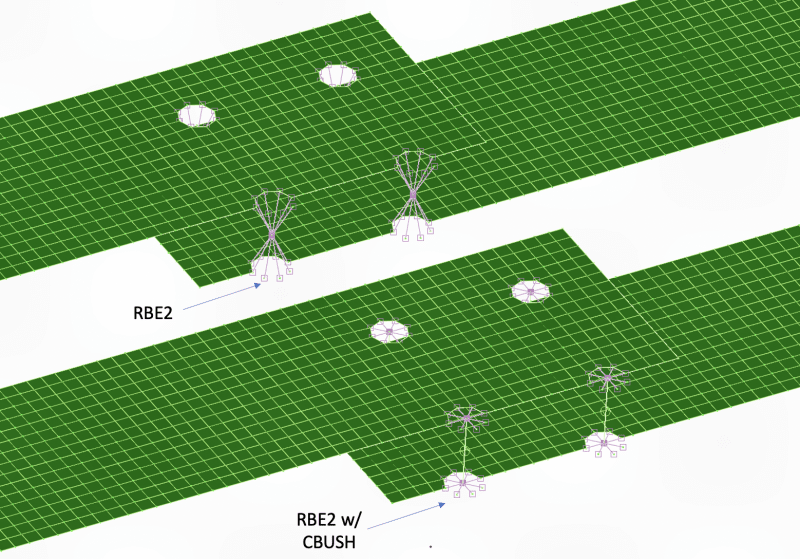
I have a question I was hoping you all could answer. A coworker sent me an FE model that he created, where he modeled a bolted joint using just an RBE2 element (with DOFs in 123) to connect the matching holes in 2 plates. I would never do this; my preferred modeling method would be to add a CBUSH element between the two holes and then connect each end to their respective plate with an RBE2.

Is it even possible to extract usable MPC forces from my coworker's model? When I plot the MPC forces marker, I get 0 lbf in every direction. Is this due to the summation of forces at the independent node or something? I know that RBE2s are infinitely stiff, so I suspect any forces/stresses at this type of joint wouldn't even be realistic or worth assessing.

I've attached a picture of a quick FEA mockup of a joint with just an RBE2 vs my preferred method of a CBUSH w/ RBE2s.
Screen_Shot_2022-09-11_at_10.03.56_PM_syzj28.png


Thanks for the input!
 
Replies continue below

Recommended for you

Ugh, both methods are awful (his more so). Sigh. Why do people insist on modelling the holes then stick an infinitely stiff element in the “hole”? (Yeah, I get it, its easy to blindly automesh using the CAD model).
 
I would not model the holes in the plates. For a two strap joint, I would connect a node in each plate (strap) with a CBUSH (if Nastran) or a fastener element (if Abaqus). For a three or more strap joint, a Ruttman type modelling method is needed to ensure fastener continuity.
 
I agree ... but sort dismissed by the OP, no?

"Hoffen wir mal, dass alles gut geht !"
General Paulus, Nov 1942, outside Stalingrad after the launch of Operation Uranus.
 
Essentially, yes. Remove the holes in the CAD model or surface before meshing. Then figure out how to force the mesh to have nodes at the fasteners. Or use a code with meshless fastener elements.
 
if you have holes (like in a 3D mesh CAD part), retain the center point/vector and delete the hoe.

if you are doing a 2D model, mesh as you like and use element results (shear/in) to derive fastener loads.

obviously use more attention for discrete high load fasteners (wing attach) than "ordinary" skin/frame of skin/stringer rivets.

"Hoffen wir mal, dass alles gut geht !"
General Paulus, Nov 1942, outside Stalingrad after the launch of Operation Uranus.
 
rb - LOL, "use element results (shear/in) to derive fastener loads" is a nearly lost art. It seems these days that if the FEM postprocessor doesn't auto plot a (often rubbish) result, then analysts have no clue how to determine it. I can't count the times I almost lost my mind when I asked for a (balanced) free body diagram and got a nearly unintelligible Patran image generated by the internal FBD generator. Sigh.
 
ditto ... sigh

"Hoffen wir mal, dass alles gut geht !"
General Paulus, Nov 1942, outside Stalingrad after the launch of Operation Uranus.
 
you can get shear flow from the FEM. sometimes directly from the elements, sometimes with some manipulation.

eg a skin splice between two elements may be directly Fxy, from FE output.
shear flow into a frame cap (or shear splice) may require some additional element addition/subtraction.

then what is the typical rivet spacing

and so the typical rivet load = (load/in)/(rivets/in)

"Hoffen wir mal, dass alles gut geht !"
General Paulus, Nov 1942, outside Stalingrad after the launch of Operation Uranus.
 
Status
Not open for further replies.
Back
Top